
Page 385 - IGUS ECS CATALOG
P. 385
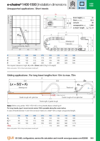
e-chains  1400·1500 | Installation dimensions                         1400
                                   ®
                                                                                              1500
                        Unsupported applications | Short travels               1392    1310

                                                                 Ba
                          Fill weight [kg/m]  8.0          ≤18  1500            Inner height [mm]  33.3
                           20
                                                                 Bi
                                                                                                21
                           10
                                                                                Pitch [mm/link]
                                                                                                30
                                                                                Links/m
                           6.0
                           4.0                             mm               21  28  corresponds to [mm]  1,000
                           2.0                                  1400            e-chain ®  length  L K  = S / 2  + K
                           1.5         FL B                               S
                                                             D           S/2
                           1.0   FL G
                                                                       32
                           0.5
                                                                          Moving end
                           0                                R             Fixed end            H  HF = H + 25
                            0      1.0   2.0    3.0                                          H - 28
                            Unsupported length FL G  / FL B  [m]  33.3               37.5
                            Travel S [m]
                            0      2.0   4.0    6.0                                       28
                        R        035    038   048    075    100   125    145    180
                        H         98    104   124    178    228   278    318    388
                        D         99    102   112    139    164   189    209    244
                        K        180    190   220    305    385   460    525    635
                        The required clearance height: H F  = H + 25mm (with 0.5kg/m fi ll weight)
                        Before using series 1400 on long travels please consult igus ® .


                        Gliding applications | For long travel lengths from 10m to max. 75m
                                                     S
                                      S/2                         S/2                    D2
                           LK = S/2 + K2                                            K2
                                  Moving end                               Fixed end
                                                                                   H2        R


                                                                  = Off set fi xed end
                                   Guide trough with glide bar         Guide trough without glide bar  HRi
                                                    Total length of guide trough
                        Note: Before using series 1400/1450/1480 on long travels please consult igus ® .
                        For long travels, igus ®  recommends series 1500 openable along the outer radius.
                        In case of travels between 4 and 10m we recommend an e-chain ®  with a longer unsupported length.
                        R        035    038   048    075    100   125    145    180
                                  70    76     96    150    100   100    100    100
                        H 2
                          +25     99    102   112    139    340   495    540    690
                        D 2
                                 180    190   220    305    600   800    940   1,170
                        K 2
                          CL      –      –     –      –     179   305    340    445
                        Before using series 1400 on long travels please consult igus ® .

                               3D CAD, confi gurators, service life calculation and more   www.igus-asean.com/E2000  383


                    06)-ASEAN-E2-1-E2000-2022.indd   383
                                                                                             05.06.23   18:35
                    06)-ASEAN-E2-1-E2000-2022.indd   383                                     05.06.23   18:35