
Page 441 - IGUS ECS CATALOG
P. 441
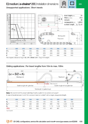
E2 medium | e-chains  255 | Installation dimensions                   255
                                               ®
                        Unsupported applications | Short travels               1392    1334


                          Fill weight [kg/m]  8.0          ≤22                  Inner height [mm]  27.8
                          20
                                                                                                24
                          10
                                                                                Pitch [mm/link]
                          6.0                              mm               24  35  Links/m     36
                          4.0                                                   corresponds to [mm]  1,000.8
                          2.0                                   Bi              e-chain ®  length  L K  = S / 2  + K
                                                                Ba
                          1.5          FL B                               S
                              FL G                           D           S/2
                          1.0
                          0.5
                                                                          Moving end
                           0                                R             Fixed end            H  HF = H + 25
                            0     1.0    2.0    3.0                                          H - 35
                            Unsupported length FL G  / FL B  [m]  27.8
                            Travel S [m]
                            0     2.0    4.0    6.0                                       35
                        R        055    075   100    125    150   175    200    225   250
                        H  0     145    185   235    285    335   385    435    485   535
                         +4
                        D        114    134   159    184    209   234    259    284   309
                        K        230    295   370    450    530   610    685    765   845
                        The required clearance height: H F  = H + 25mm (with 1.5kg/m fi ll weight)


                        Gliding applications | For travel lengths from 10m to max. 100m
                                                     S
                                      S/2                         S/2                    D2
                           LK = S/2 + K2                                            K2
                                  Moving end                               Fixed end
                                                                                   H2        R


                                                                  = Off set fi xed end
                                   Guide trough with glide bar         Guide trough without glide bar  HRi
                                                    Total length of guide trough
                        Note: We recommend the project planning of such a system to be carried out by igus ® .
                        In case of travels between 4 and 10m we recommend an e-chain ®  with a longer unsupported length.

                        R        055    075   100    125    150   175    200    225   250
                                 110    150   100    100    100   100    100    100   100
                        H 2
                          +25    114    134   380    495    570   665    740   1,040  1,130
                        D 2
                                 230    295   612    806    945   1,112  1,223  1,610  1,779
                        K 2
                          CL      –      –    222    322    372   437    497     *    822
                        *upon request


                               3D CAD, confi gurators, service life calculation and more   www.igus-asean.com/E2000  439


                    06)-ASEAN-E2-1-E2000-2022.indd   439                                     05.06.23   18:35
                                                                                             05.06.23   18:35
                    06)-ASEAN-E2-1-E2000-2022.indd   439