
Page 457 - IGUS ECS CATALOG
P. 457
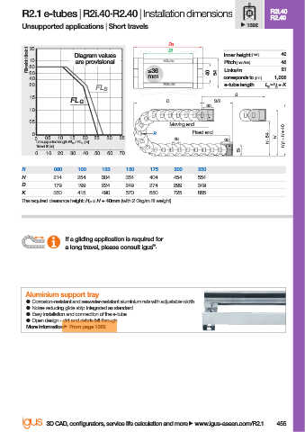
R2.1 e-tubes | R2i.40·R2.40 | Installation dimensions                R2i.40
                                                                                             R2.40
                        Unsupported applications | Short travels                       1392

                                                                 Ba
                          Fill weight [kg/m]  10  Diagram values  R2.40         Inner height [mm]  40
                           20
                                                                 Bi
                                       are provisional
                                                                                                48
                                                                                Pitch [mm/link]
                          8.0
                          6.0                              ≤36              40  54  Links/m     21
                          4.0                              mm                   corresponds to [mm]  1,008
                          2.0                                   R2i.40          e-tube length  L K  = S / 2  + K
                                             FL B
                                                                                   S
                          1.5
                                      FL G                      D             S/2
                                                                            60
                          1.0
                          0.5
                                                                 Moving end
                           0                                 R          Fixed end                H F  = H + 40
                            0  0.5  1.0  1.5  2.0  2.5  3.0  3.5  48            60           H - 54  H
                            Unsupported length FL G  / FL B  [m]
                            Travel S [m]
                                                                                     54
                            0  1.0  2.0  3.0  4.0  5.0  6.0  7.0
                        R        080    100   125    150    175   200    250
                        H        214    254   304    354    404   454    554
                        D        179    199   224    249    274   299    349
                        K        350    415   490    570    650   725    885
                        The required clearance height: H F  = H + 40mm (with 2.0kg/m fi ll weight)


                                    If a gliding application is required for
                                                            ®
                                    a long travel, please consult igus .


                          Aluminium support tray
                          ●  Corrosion-resistant and seawater-resistant aluminium rails with adjustable width
                          ●  Noise-reducing glide strip integrated as standard
                          ●  Easy installation and connection of the e-tube
                          ●  Open design - dirt and debris fall through
                          More information   From page 1362


                               3D CAD, confi gurators, service life calculation and more   www.igus-asean.com/R2.1  455


                    07)-ASEAN-E-TUBES-2022.indd   455                                        05.06.23   18:39
                                                                                             05.06.23   18:39
                    07)-ASEAN-E-TUBES-2022.indd   455