
Page 507 - IGUS ECS CATALOG
P. 507
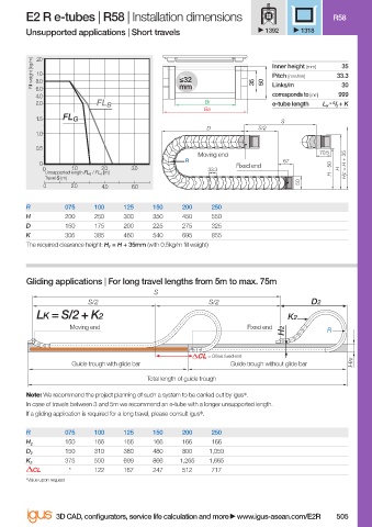
E2 R e-tubes | R58 | Installation dimensions                          R58
                        Unsupported applications | Short travels               1392    1318


                           20
                          Fill weight [kg/m]  8.0          ≤32              35  50  Inner height [mm]  33.3
                                                                                                35
                           10
                                                                                Pitch [mm/link]
                                                                                                30
                                                                                Links/m
                           6.0
                           4.0                             mm                   corresponds to [mm]  999
                           2.0          FL B                     Bi             e-tube length  L K  = S / 2  + K
                                                                 Ba
                           1.5   FL G                                             S
                                                                 D           S/2
                           1.0
                           0.5
                                                               Moving end                  70.5
                                                            R                      67
                           0                                            Fixed end                H F  = H + 35
                            0      1.0   2.0    3.0               33.3                        H - 50  H
                             Unsupported length FL G  / FL B  [m]
                             Travel S [m]
                                                                                      50
                            0      2.0    4.0   6.0
                        R        075    100   125    150    200   250
                        H        200    250   300    350    450   550
                        D        150    175   200    225    275   325
                        K        305    385   460    540    695   855
                        The required clearance height: H F  = H + 35mm (with 0.5kg/m fi ll weight)


                        Gliding applications | For long travel lengths from 5m to max. 75m
                                                     S
                                      S/2                         S/2                    D2
                           LK = S/2 + K2                                            K2
                                  Moving end                               Fixed end
                                                                                   H2        R


                                                                  = Off set fi xed end
                                   Guide trough with glide bar         Guide trough without glide bar  HRi
                                                    Total length of guide trough
                        Note: We recommend the project planning of such a system to be carried out by igus ® .
                        In case of travels between 3 and 5m we recommend an e-tube with a longer unsupported length.
                        If a gliding application is required for a long travel, please consult igus ® .
                        R        075    100   125    150    200   250
                                 150    166   166    166    166   166
                        H 2
                                 150    310   380    480    800   1,050
                        D 2
                                 375    500   699    866   1,265  1,665
                        K 2
                          CL      *     122   167    247    512   717
                        *Value upon request

                               3D CAD, confi gurators, service life calculation and more   www.igus-asean.com/E2R  505


                    07)-ASEAN-E-TUBES-2022.indd   505
                    07)-ASEAN-E-TUBES-2022.indd   505                                        05.06.23   18:39
                                                                                             05.06.23   18:39