
Page 557 - IGUS ECS CATALOG
P. 557
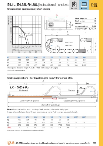
E4.1L | E4.38L·R4.38L | Installation dimensions                      E4.38L
                                                                                             R4.38L
                        Unsupported applications | Short travels               1392    1316

                                                                Ba
                           50
                          Fill weight [kg/m]  40                                Inner height [mm]  38
                                                                Bi
                                                                                                56
                                                                                Pitch [mm/link]
                           30
                           20                              ≤34              38  54  Links/m     18
                                                           mm                   corresponds to [mm]  1,008
                           10
                          8.0                                                   e-chain ®  length  L K  = S / 2  + K
                          6.0
                          4.0                                             S
                          2.0
                                          FL B               D           S/2
                          1.5     FL G
                          1.0
                          0.5                                           Moving end
                           0                                            Fixed end
                            0  0.5 1.0  1.5  2.0 2.5 3.0  3.5  4.0 4.5  5.0  R  56               H F  = H + 40
                            Unsupported length FL G  / FL B  [m]                             H - 54  H
                            Travel S [m]
                                                                                          54
                            0    2.0  4.0  6.0  8.0  10
                        R        063 1)  075 1)  100 1)  125  150  175   200    250   300
                        H        180    204   254    304    354   404    454    554   654
                        D        174    186   211    236    261   286    311    361   411
                        K        310    350   430    505    585   665    745    900   1,055
                        The required clearance height: H F  = H + 40mm (with 2.0kg/m fi ll weight)
                        1) Radius not available for e-tubes


                        Gliding applications | For travel lengths from 10m to max. 80m
                                                     S
                                      S/2                         S/2                    D2
                           LK = S/2 + K2                                            K2
                                  Moving end                               Fixed end
                                                                                   H2        R


                                                                  = Off set fi xed end
                                   Guide trough with glide bar         Guide trough without glide bar  HRi
                                                    Total length of guide trough
                        Note: We recommend the project planning of such a system to be carried out by igus ® .
                        In case of travels between 5 and 10m we recommend an e-chain ®  with a longer unsupported length.

                        R        063 1)  075 1)  100 1)  125  150  175   200   250 2)  300 2)
                                 180    204    96    96     96     96    96      –     –
                        H 2
                                 174    186   370    470    500   655    770     –     –
                        D 2
                                 310    350   616    784    896   1,120  1,288   –     –
                        K 2
                          CL      –      –    160    210    240   370    460     –     –
                        2) Radius not suitable for long travel applications. Please consult igus ® .


                               3D CAD, confi gurators, service life calculation and more   www.igus-asean.com/E4.1L  555


                    08)-ASEAN-E4-1LEAN-2022.indd   555                                       05.06.23   18:40
                                                                                             05.06.23   18:40
                    08)-ASEAN-E4-1LEAN-2022.indd   555