
Page 635 - IGUS ECS CATALOG
P. 635
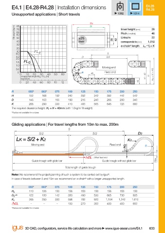
E4.1 | E4.28·R4.28 | Installation dimensions                         E4.28
                                                                                             R4.28
                        Unsupported applications | Short travels               1392    1314

                                                                Ba
                                                                Bi
                          Fill weight [kg/m]  75                                Inner height [mm]  28
                           85
                           65
                                                                                                46
                                                                                Pitch [mm/link]
                           60
                                                                                                22
                           50
                                                           mm
                           40                              ≤25              28  42  Links/m   1,012
                                                                                corresponds to [mm]
                           30
                                                                                e-chain ®  length  L K  = S / 2  + K
                           20
                           10
                          8.0       FL B                                 S
                          4.0                               D            S/2
                          2.0
                          1.5  FL G
                          1.0
                                                                       Moving end
                          0.5
                           0                                R    46     Fixed end                    40
                            0  1.0  2.0  3.0  4.0  5.0  6.0
                             Unsupported length FL G  / FL B  [m]                            H - 42  H  H F  = H +
                             Travel S [m]
                            0  2.0  4.0  6.0  8.0  10  12                                42
                        R        055*   063*  075    100    125   150    175    200   250
                        H        152    168   192    242    292   342    392    442   542
                        D        145    153   165    190    215   240    265    290   340
                        K        265    290   330    410    485   565    645    725   880
                        The required clearance height: H F  = H + 40mm (with 1.0kg/m fi ll weight)
                        *Radius not available for e-tubes
                        Gliding applications | For travel lengths from 10m to max. 200m
                                                     S
                                      S/2                         S/2                    D2
                           LK = S/2 + K2                                            K2
                                  Moving end                               Fixed end
                                                                                   H2        R


                                                                  = Off set fi xed end
                                   Guide trough with glide bar         Guide trough without glide bar  HRi
                                                    Total length of guide trough
                        Note: We recommend the project planning of such a system to be carried out by igus ® .
                        In case of travels between 5 and 10m we recommend an e-chain ®  with a longer unsupported length.

                        R        055*   063*  075    100    125   150    175    200   250
                                 110    126   150    158    158   158    158    158   158
                        H 2
                          +25    122    130   142    350    490   530    665    730   935
                        D 2
                                 265    290   330    598    782   920    1,104  1,242  1.610
                        K 2
                          CL      –      –     –     150    270   300    400    450   600
                        *Radius not available for e-tubes


                               3D CAD, confi gurators, service life calculation and more   www.igus-asean.com/E4.1  633


                    10)-ASEAN-E4-1-2022.indd   633                                           05.06.23   18:48
                    10)-ASEAN-E4-1-2022.indd   633
                                                                                             05.06.23   18:48