
Page 677 - IGUS ECS CATALOG
P. 677
E4.80
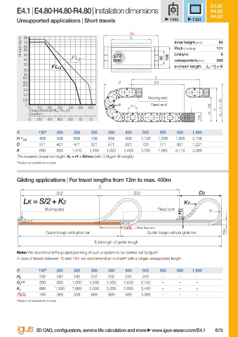
E4.1 | E4.80·H4.80·R4.80 | Installation dimensions H4.80
R4.80
Unsupported applications | Short travels 1392 1324
Ba
Bi
85
Fill weight [kg/m] 75 Inner height [mm] 111
80
65
Pitch [mm/link]
60
50
40 FL B ≤72 80 108 Links/m 999 9
mm
corresponds to [mm]
30 = S / 2 + K
FL G e-chain ® length L K
20
10
8.0 S
4.0 D S/2
2.0
1.5
1.0
Moving end
0.5
0 R 111 Fixed end
0 1.0 2.0 3.0 4.0 5.0 6.0 H F = H + 60
Unsupported length FL G / FL B [m] H - 108 H
Travel S [m]
108
0 2.0 4.0 6.0 8.0 10 12
R 150* 200 250 300 350 400 500 550 600 1,000
H -0 408 508 608 708 808 908 1,108 1,208 1.308 2,108
+25
D 371 421 471 521 571 621 721 771 821 1,221
K 695 855 1,010 1,165 1,325 1,480 1,795 1,950 2,110 3,365
The required clearance height: H F = H + 60mm (with 3.0kg/m fi ll weight)
*Radius not available for e-tubes
Gliding applications | For travel lengths from 12m to max. 400m
S
S/2 S/2 D2
LK = S/2 + K2 K2
Moving end Fixed end
H2 R
= Off set fi xed end
Guide trough with glide bar Guide trough without glide bar HRi
Total length of guide trough
Note: We recommend the project planning of such a system to be carried out by igus ® .
In case of travels between 10 and 12m we recommend an e-chain ® with a longer unsupported length.
R 150* 200 250 300 350 400 500 550 600 1,000
242 242 242 242 242 242 242 – – –
H 2
+25 550 800 1,000 1,200 1,450 1,600 2,100 – – –
D 2
890 1,330 1,665 2,000 2,330 2,660 3,440 – – –
K 2
CL 189 389 539 689 889 989 1,389 – – –
*Radius not available for e-tubes
3D CAD, confi gurators, service life calculation and more www.igus-asean.com/E4.1 675
10)-ASEAN-E4-1-2022.indd 675 05.06.23 18:48
05.06.23 18:48
10)-ASEAN-E4-1-2022.indd 675