Page 689 - IGUS ECS CATALOG
P. 689

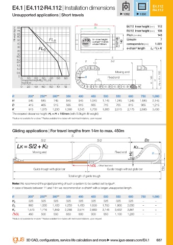
E4.1 | E4.112·R4.112 | Installation dimensions                Steel  E4.112
                                                                                             R4.112
                        Unsupported applications | Short travels               1392    1350

                                                                Ba              E4.112 Inner height [mm]  112
                                                                Bi
                          Fill weight [kg/m]  75                                R4.112 Inner height [mm]  108
                           85
                           65
                                                                                               143
                                                                                Pitch [mm/link]
                           60
                           50
                                                                e-chain ®  112mm
                                                           mm
                           40             FL B             ≤100  hi - inner height:  112/108  140  Links/m   1.001 7
                                                                e-tube 108mm
                                                                                corresponds to [mm]
                           30                                                   e-chain ®  length  L K / 2  + K
                                                                                              = S
                                     FL G
                           20
                           10
                           8.0                                           S
                           4.0
                          2.0                               D            S/2
                          1.5
                          1.0
                          0.5                                              Moving end
                           0                                R
                            0  1.0  2.0  3.0  4.0  5.0  6.0            Fixed end                 H F  = H + 100
                             Unsupported length FL G  / FL B  [m]  143                       H - 140  H
                             Travel S [m]
                            0  2.0  4.0  6.0  8.0  10  12                              140
                        R       200*  250**  300**  350  400   450   500   550   600   750   1,000
                        H       545   645    745   845   945  1,045  1,145  1,245  1,345  1,645  2,145
                        D       415   465    515   565   615   665   715   765   815   965   1,215
                        K       915   1,075  1,230  1,390  1,545  1,700  1,860  2,015  2,175  2,645  3,430
                        The required clearance height: H F  = H + 100mm (with 5.0kg/m fi ll weight)
                        *Radius not available for e-tubes **Radius available for e-tubes with technical limitations, upon request
                        Gliding applications | For travel lengths from 14m to max. 450m
                                                     S
                                      S/2                         S/2                    D2
                           LK = S/2 + K2                                            K2
                                  Moving end                               Fixed end
                                                                                   H2        R

                                                                  = Off set fi xed end
                                   Guide trough with glide bar         Guide trough without glide bar  HRi
                                                    Total length of guide trough
                        Note: We recommend the project planning of such a system to be carried out by igus ® .
                        In case of travels between 11 and 14m we recommend an e-chain ®  with a longer unsupported length.

                        R       200*  250**  300**  350  400   450   500   550   600   750   1,000
                                325   325    325   325   325   325   325   325   325    –     –
                        H 2
                                900   1,000  1,100  1,250  1,450  1,600  1,700  1,900  2,050  –  –
                        D 2
                                1,573  1,716  1,859  2,288  2,574  2,860  3,146  3,432  3,861  –  –
                        K 2
                          CL    450   500    550   650   800   900   950  1,100  1,200  –     –
                        *Radius not available for e-tubes **Radius available for e-tubes with technical limitations, upon request


                               3D CAD, confi gurators, service life calculation and more   www.igus-asean.com/E4.1  687


                    10)-ASEAN-E4-1-2022.indd   687                                           05.06.23   18:49
                                                                                             05.06.23   18:49
                    10)-ASEAN-E4-1-2022.indd   687
   684   685   686   687   688   689   690   691   692   693   694