
Page 697 - IGUS ECS CATALOG
P. 697
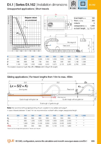
E4.1 | Series E4.162 | Installation dimensions                Steel  E4.162
                        Unsupported applications | Short travels               1392   upon request

                                                                Ba
                                                                Bi
                          100
                          Fill weight [kg/m]  90  Diagram values                Inner height [mm]  162 5
                           80
                                       are provisional
                                                                                               200
                                                                                Pitch [mm/link]
                           70
                                                                                Links/m
                           60
                                                           mm
                           50                              ≤145             162  195  corresponds to [mm]  1,000
                                      FL B
                           40                                                   e-chain ®  length  L K  = S / 2  + K
                           30
                           20
                           10   FL G                                     S
                           6.0                              D            S/2
                           2.0
                           1.0
                           0.5                                             Moving end
                           0                                R
                            0 1.0 2.0 3.0 4.0 5.0  6.0 7.0 8.0 9.0 10 11 12  200  Fixed end      H F  = H + 100
                            Unsupported length FL G  / FL B  [m]                             H - 195  H
                            Travel S [m]
                            0   4.0  8.0  12  16  20  24                               195
                        R       250   300    350   400   450   500   550   600   750   1,000
                        H       700   800    900  1,000  1,100  1,200  1,300  1,400  1,700  2,200
                        D       648   698    748   798   848   898   948   998   1,148  1,398
                        K       1,190  1,345  1,500  1,660  1,815  1,975  2,130  2,285  2,760  3,545
                        The required clearance height: H F  = H + 100mm (with 5.0kg/m fi ll weight)
                        Gliding applications | For travel lengths from 14m to max. 450m
                                                     S
                                      S/2                         S/2                    D2
                           LK = S/2 + K2                                            K2
                                  Moving end                               Fixed end
                                                                                   H2        R


                                                                  = Off set fi xed end
                                   Guide trough with glide bar         Guide trough without glide bar  HRi
                                                    Total length of guide trough
                        Note: We recommend the project planning of such a system to be carried out by igus ® .
                        In case of travels between 12 and 14m we recommend an e-chain ®  with a longer unsupported length.

                        R       250   300    350   400   450   500   550   600   750   1,000
                                 *    580    580   580   580   580   580   580    **    **
                        H 2
                                 *    950   1,050  1,350  1,600  1,950  2,050  2,400  **  **
                        D 2
                                 *    1,600  1,800  2,400  2,800  3,200  3,400  3,800  **  **
                        K 2
                          CL     *    300    350   600   800  1,100  1,150  1,450  **   **
                        *Values such as unsupported applications **Values upon request


                               3D CAD, confi gurators, service life calculation and more   www.igus-asean.com/E4.1  695


                    10)-ASEAN-E4-1-2022.indd   695                                           05.06.23   18:49
                                                                                             05.06.23   18:49
                    10)-ASEAN-E4-1-2022.indd   695