
Page 747 - IGUS ECS CATALOG
P. 747
15050
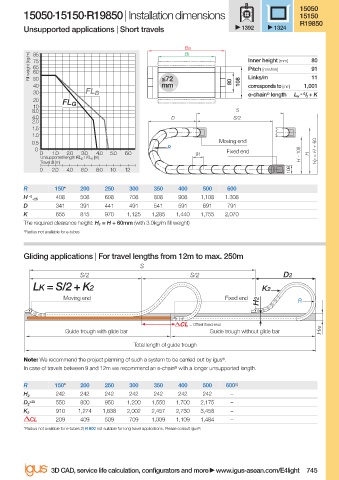
15050·15150·R19850 | Installation dimensions 15150
R19850
Unsupported applications | Short travels 1392 1324
Ba
Bi
Fill weight [kg/m] 75 Inner height [mm] 80
85
65
91
Pitch [mm/link]
60
11
50
mm
40 ≤72 80 108 Links/m 1,001
corresponds to [mm]
30 FL B e-chain ® length L K = S / 2 + K
20
FL G
10
8.0 S
4.0 D S/2
2.0
1.5
1.0
0.5 Moving end
R
0 Fixed end H F = H + 60
0 1.0 2.0 3.0 4.0 5.0 6.0 91 H - 108 H
Unsupported length FL G / FL B [m]
Travel S [m]
0 2.0 4.0 6.0 8.0 10 12 108
R 150* 200 250 300 350 400 500 600
H -0 408 508 608 708 808 908 1,108 1.308
+25
D 341 391 441 491 541 591 691 791
K 655 815 970 1,125 1,285 1,440 1,755 2,070
The required clearance height: H F = H + 60mm (with 3.0kg/m fi ll weight)
*Radius not available for e-tubes
Gliding applications | For travel lengths from 12m to max. 250m
S
S/2 S/2 D2
LK = S/2 + K2 K2
Moving end Fixed end
H2 R
= Off set fi xed end
Guide trough with glide bar Guide trough without glide bar HRi
Total length of guide trough
Note: We recommend the project planning of such a system to be carried out by igus ® .
In case of travels between 9 and 12m we recommend an e-chain ® with a longer unsupported length.
R 150* 200 250 300 350 400 500 600 1)
242 242 242 242 242 242 242 –
H 2
+25 550 800 950 1,200 1,550 1,700 2,175 –
D 2
910 1,274 1,638 2,002 2,457 2,730 3,458 –
K 2
CL 209 409 509 709 1,009 1,109 1,484 –
*Radius not available for e-tubes 2) R 600 not suitable for long travel applications. Please consult igus ® .
3D CAD, service life calculation, confi gurators and more www.igus-asean.com/E4light 745
11)-ASEAN-E4LIGHT-OLD_YE-2022.indd 745 05.06.23 18:51
11)-ASEAN-E4LIGHT-OLD_YE-2022.indd 745
05.06.23 18:51