
Page 891 - IGUS ECS CATALOG
P. 891
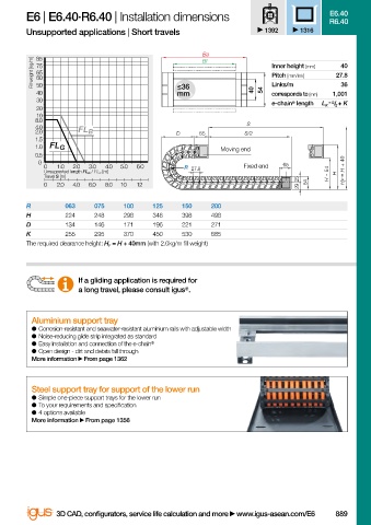
E6 | E6.40·R6.40 | Installation dimensions                           E6.40
                                                                                             R6.40
                        Unsupported applications | Short travels               1392    1316

                                                                Ba
                          Fill weight [kg/m]  75                                Inner height [mm]  27.8
                           85
                                                                Bi
                                                                                                40
                           65
                                                                                Pitch [mm/link]
                           60
                                                                                                36
                           50
                                                           mm
                           40                              ≤36              40  54  Links/m   1,001
                                                                                corresponds to [mm]
                           30
                                                                                e-chain ®  length  L K  = S / 2  + K
                           20
                           10
                          8.0                                              S
                          4.0
                          2.0       FL B                   D    65        S/2
                          1.5
                          1.0  FL G
                                                                     Moving end
                          0.5
                           0
                            0  1.0  2.0  3.0  4.0  5.0  6.0  R 27.8       Fixed end  65
                            Unsupported length FL G  / FL B  [m]                             H - 54   H  H F   = H + 40
                            Travel S [m]
                                                                                      25
                            0  2.0  4.0  6.0  8.0  10  12                             29  54
                        R        063    075   100    125    150   200
                        H        224    248   298    348    398   498
                        D        134    146   171    196    221   271
                        K        255    295   370    450    530   685
                        The required clearance height: H F  = H + 40mm (with 2.0kg/m fi ll weight)
                                    If a gliding application is required for
                                    a long travel, please consult igus .
                                                            ®
                          Aluminium support tray
                          ●  Corrosion-resistant and seawater-resistant aluminium rails with adjustable width
                          ●  Noise-reducing glide strip integrated as standard
                          ●  Easy installation and connection of the e-chain ®
                          ●  Open design - dirt and debris fall through
                          More information   From page 1362


                          Steel support tray for support of the lower run
                          ●  Simple one-piece support trays for the lower run
                          ●  To your requirements and specifi cation
                          ●  4 options available
                          More information   From page 1356


                               3D CAD, confi gurators, service life calculation and more   www.igus-asean.com/E6  889


                    13)-ASEAN-CLEAN-E6-E3-T3-TH3-2022.indd   889
                                                                                             05.06.23   18:55
                    13)-ASEAN-CLEAN-E6-E3-T3-TH3-2022.indd   889                             05.06.23   18:55