
Page 1297 - IGUS ECS CATALOG
P. 1297
Guide troughs | Long travels | Introduction Alu Steel
1298 1326
B Ri = Ba + 4
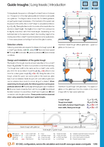
For long travels, the upper run of the igus ® e-chains ® rests on the lower Ba
run. The upper run of the chain glides partly on the lower run and partly Bi
on a glide bar. The diagram below shows this. For lateral guidance,
an igus ® guide trough is necessary. If the fi xed end of the system can
ha
be placed in the centre, the e-chain ® length is calculated as follows:
. Placing the fi xed end in the centre of the travel off ers the H Ri
shortest e-chain ® length. The length of the e-chain ® then corresponds
to slightly more than half of the travel length. Depending on the ha
technical data for the selected e-chain ® , the mounting height of the
moving end of the e-chain ® must be lowered on some applications.
In these cases please contact igus ® and we'd be glad to advise.
Selection criteria Aluminium SuperTrough without glide bars - upper run
Following parameters are required for design of a trough system: ● glides on the lower run
e-chain ® type (Series, width Bi, radius R) ● Travel and travel speed
● Fill weight ● Acceleration ● Lateral acceleration ● Environmental
B Ri = Ba + 4
conditions Ba
Bi
Design and installation of the guide trough
The height of the trough must be at least twice that of the e-chain ®
ha
height: . The sides must provide a chamfered opening.
The trough inner width is the same as the e-chain ® outer width, H Ri
plus 4mm for an aluminium SuperTrough and plus
5mm for a steel guide trough . Along the side of the
trough, where the upper run cannot glide on the lower run, glide
bars must be installed. Guide troughs with and without glide bars
can be obtained from stock for almost all igus ® e-chains ® . When
assembling the trough parts, the following points must be given
particular attention: ● Properly align all trough parts upon installation Aluminium SuperTrough with glide bars. The upper run
● All screw heads should be fl ush with the trough ● Smooth level glides on the glide bars from the middle of the travel
transition between the end of the e-chain ® and the glide bars ● Solid (image with the high-speed glide bar)
connection with the glide surface. These points must be observed
when using assembly-friendly igus ® guide troughs.
S
e-chain ® length L K = / 2 + K 2
Trough inner height H Ri ≥ 2 x ha
Inner width, Aluminium SuperTroughs B Ri = Ba + 4
Inner width, Steel guide trough B Ri = Ba + 5
S
S/2 S/2 D2
K2
H2 R
Guide trough with glide bar Guide trough without glide bar HRI
Total length of guide trough
Trough set Ba = Outer e-chain ® width S = Travel H Ri = Trough inner height H 2 = Installation height (with lowered moving end)
Installation set Bi = Inner e-chain ® width S / 2 = Half length of travel H Ra = Trough outer height D 2 = Over length for long travels gliding
glide bar R = Bend radius B Ri = Trough inner width ha = e-chain ® outer height K 2 = Add-on (with lowered moving end)
C-profi le CL = Off set fi xed end B Ra = Trough outer width L K = e-chain ® length H F = Required clearance height
3D CAD, confi gurators, service life calculation and more www.igus-asean.com/guide 1295
05.06.23 19:14
18)-ASEAN-GUIDE_TROUGHS_ALU_STEEL-2022.indd 1295
18)-ASEAN-GUIDE_TROUGHS_ALU_STEEL-2022.indd 1295 05.06.23 19:14