
Page 397 - IGUS ECS CATALOG
P. 397
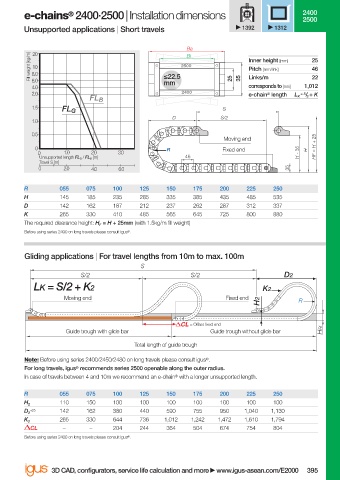
e-chains  2400·2500 | Installation dimensions                         2400
                                   ®
                                                                                              2500
                        Unsupported applications | Short travels               1392    1312

                                                                 Ba
                          20
                          Fill weight [kg/m]  8.0          ≤22.5  2500          Inner height [mm]  25
                                                                 Bi
                          10
                                                                                                46
                                                                                Pitch [mm/link]
                                                                                Links/m
                                                                                                22
                          6.0
                          4.0                              mm               25  35  corresponds to [mm]  1,012
                          2.0                                   2400            e-chain ®  length  L K  = S / 2  + K
                                         FL B
                          1.5                                             S
                                  FL G
                                                             D           S/2
                          1.0
                          0.5
                                                                          Moving end
                           0                                R             Fixed end            H  HF = H + 25
                            0     1.0    2.0    3.0                                          H - 35
                            Unsupported length FL G  / FL B  [m]  46
                            Travel S [m]
                            0     2.0    4.0    6.0                                       35
                        R        055    075   100    125    150   175    200    225   250
                        H        145    185   235    285    335   385    435    485   535
                        D        142    162   187    212    237   262    287    312   337
                        K        265    330   410    485    565   645    725    800   880
                        The required clearance height: H F  = H + 25mm (with 1.5kg/m fi ll weight)
                        Before using series 2400 on long travels please consult igus ® .

                        Gliding applications | For travel lengths from 10m to max. 100m
                                                     S
                                      S/2                         S/2                    D2
                           LK = S/2 + K2                                            K2
                                  Moving end                               Fixed end
                                                                                   H2        R


                                                                  = Off set fi xed end
                                   Guide trough with glide bar         Guide trough without glide bar  HRi
                                                    Total length of guide trough
                        Note: Before using series 2400/2450/2480 on long travels please consult igus ® .
                        For long travels, igus ®  recommends series 2500 openable along the outer radius.
                        In case of travels between 4 and 10m we recommend an e-chain ®  with a longer unsupported length.
                        R        055    075   100    125    150   175    200    225   250
                                 110    150   100    100    100   100    100    100   100
                        H 2
                          +25    142    162   380    440    590   755    950   1,040  1,130
                        D 2
                                 265    330   644    736   1,012  1,242  1,472  1,610  1,794
                        K 2
                          CL      –      –    204    244    364   504    674    754   804
                        Before using series 2400 on long travels please consult igus ® .

                               3D CAD, confi gurators, service life calculation and more   www.igus-asean.com/E2000  395


                    06)-ASEAN-E2-1-E2000-2022.indd   395
                                                                                             05.06.23   18:35
                    06)-ASEAN-E2-1-E2000-2022.indd   395                                     05.06.23   18:35