
Page 513 - IGUS ECS CATALOG
P. 513
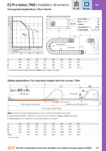
E2 R e-tubes | R68 | Installation dimensions                          R68
                        Unsupported applications | Short travels               1392    1320


                           20
                          Fill weight [kg/m]  8.0          ≤42                  Inner height [mm]  45
                           10
                                                                                                36
                                                                                Pitch [mm/link]
                          6.0                              mm               45  64  Links/m     28
                          4.0                                                   corresponds to [mm]  1,008
                          2.0                                    Bi             e-tube length  L K  = S / 2  + K
                                              FL B               Ba
                          1.5
                                    FL G                                          S
                                                                 D           S/2
                          1.0
                          0.5
                                                                Moving end                 72
                                                             R                     72
                           0                                            Fixed end             4  H F  = H + 40
                            0     1.0    2.0    3.0               36                          H - 6  H
                            Unsupported length FL G  / FL B  [m]
                            Travel S [m]
                                                                                      64
                            0     2.0    4.0    6.0
                        R        100    125   150    175    200   225    250    300
                        H        264    314   364    414    464   514    564    664
                        D        186    211   236    261    286   311    336    386
                        K        390    465   545    625    705   780    860   1,015
                        The required clearance height: H F  = H + 40mm (with 2.5kg/m fi ll weight)


                        Gliding applications | For long travel lengths from 6m to max. 100m
                                                     S
                                      S/2                         S/2                    D2
                           LK = S/2 + K2                                            K2
                                  Moving end                               Fixed end
                                                                                   H2        R


                                                                  = Off set fi xed end
                                   Guide trough with glide bar         Guide trough without glide bar  HRi
                                                    Total length of guide trough
                        Note: We recommend the project planning of such a system to be carried out by igus ® .
                        In case of travels between 4 and 6m we recommend an e-tube with a longer unsupported length.
                        If a gliding application is required for a long travel, please consult igus ® .
                        R        100    125   150    175    200   225    250    300
                                 201    220   220    220    220   220    220    220
                        H 2
                                 200    370   440    540    650   700    850   1,050
                        D 2
                                 500    648   792    900   1,116  1,269  1,476  1,800
                        K 2
                          CL      *     164   204    294    364   439    514    664
                        *Value upon request

                               3D CAD, confi gurators, service life calculation and more   www.igus-asean.com/E2R  511


                    07)-ASEAN-E-TUBES-2022.indd   511                                        05.06.23   18:39
                                                                                             05.06.23   18:39
                    07)-ASEAN-E-TUBES-2022.indd   511