
Page 575 - IGUS ECS CATALOG
P. 575
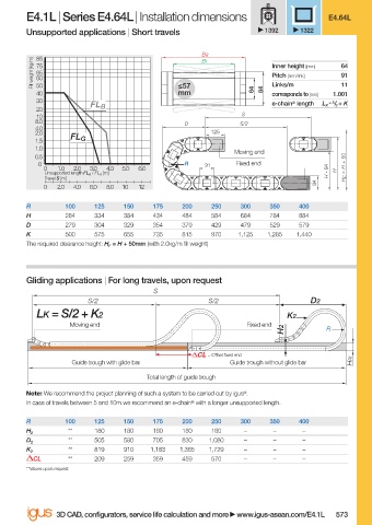
E4.1L | Series E4.64L | Installation dimensions                      E4.64L
                        Unsupported applications | Short travels               1392    1322

                                                                Ba
                           85
                          Fill weight [kg/m]  75                                Inner height [mm]  64
                                                                Bi
                           65
                                                                                                91
                                                                                Pitch [mm/link]
                           60
                                                                                                11
                           50
                                                           mm
                           40                              ≤57              64  84  Links/m   1.001
                                                                                corresponds to [mm]
                           30                                                   e-chain ®  length   = S / 2  + K
                                       FL B                                                 L K
                           20
                           10                                            S
                          8.0                               D            S/2
                          4.0
                          2.0                                     125
                                  FL G
                          1.5
                          1.0
                                                                        Moving end
                          0.5                                                                     + 50
                           0                                R    91     Fixed end
                            0  1.0  2.0  3.0  4.0  5.0  6.0                                  84
                            Unsupported length FL G  / FL B  [m]                             H -   H  H F  = H
                            Travel S [m]
                                                                                          84
                            0  2.0  4.0  6.0  8.0  10  12
                        R        100    125   150    175    200   250    300    350   400
                        H        284    334   384    434    484   584    684    784   884
                        D        279    304   329    354    379   429    479    529   579
                        K        500    575   655    735    815   970    1,125  1,285  1,440
                        The required clearance height: H F  = H + 50mm (with 2.0kg/m fi ll weight)
                        Gliding applications | For long travels, upon request
                                                     S
                                      S/2                         S/2                    D2
                           LK = S/2 + K2                                            K2
                                  Moving end                               Fixed end
                                                                                   H2        R

                                                                  = Off set fi xed end
                                   Guide trough with glide bar         Guide trough without glide bar  HRi
                                                    Total length of guide trough
                        Note: We recommend the project planning of such a system to be carried out by igus ® .
                        In case of travels between 5 and 10m we recommend an e-chain ®  with a longer unsupported length.

                        R        100    125   150    175    200   250    300    350   400
                                  **    180   180    180    180   180     –      –     –
                        H 2
                                  **    505   580    705    830   1,080   –      –     –
                        D 2
                                  **    819   910    1,183  1,365  1,729  –      –     –
                        K 2
                          CL      **    209   259    359    459   570     –      –     –
                        **Values upon request


                               3D CAD, confi gurators, service life calculation and more   www.igus-asean.com/E4.1L  573


                    08)-ASEAN-E4-1LEAN-2022.indd   573                                       05.06.23   18:41
                    08)-ASEAN-E4-1LEAN-2022.indd   573
                                                                                             05.06.23   18:41