
Page 739 - IGUS ECS CATALOG
P. 739
14550
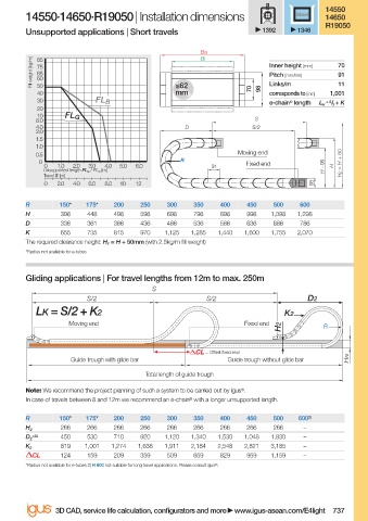
14550·14650·R19050 | Installation dimensions Steel 14650
R19050
Unsupported applications | Short travels 1392 1346
Ba
Bi
Fill weight [kg/m] 75 Inner height [mm] 70
85
65
91
Pitch [mm/link]
60
11
50
mm
40 ≤62 70 98 Links/m 1,001
corresponds to [mm]
30 FL B e-chain ® length L K = S / 2 + K
20
10 FL G
8.0 S
4.0 D S/2
2.0
1.5
1.0
0.5 Moving end
0 R Fixed end H F = H + 50
0 1.0 2.0 3.0 4.0 5.0 6.0 91 H - 98 H
Unsupported length FL G / FL B [m]
Travel S [m]
0 2.0 4.0 6.0 8.0 10 12 98
R 150* 175* 200 250 300 350 400 450 500 600
H 398 448 498 598 698 798 898 998 1,098 1,298
D 336 361 386 436 486 536 586 636 686 786
K 655 735 815 970 1,125 1,285 1,440 1,600 1,755 2,070
The required clearance height: H F = H + 50mm (with 2.5kg/m fi ll weight)
*Radius not available for e-tubes
Gliding applications | For travel lengths from 12m to max. 250m
S
S/2 S/2 D2
LK = S/2 + K2 K2
Moving end Fixed end
H2 R
= Off set fi xed end
Guide trough with glide bar Guide trough without glide bar HRi
Total length of guide trough
Note: We recommend the project planning of such a system to be carried out by igus ® . We recommend the project planning of such a system to be carried out by igus ® .
Note:
In case of tr
In case of travels between 8 and 12m we recommend an e-chain ® with a longer unsupported length.avels between 8 and 12m we recommend an e-chain ® with a longer unsupported length.
R 150* 175* 200 250 300 350 400 450 500 600 2)
266 266 266 266 266 266 266 266 266 –
H 2
+25 450 530 710 920 1,120 1,340 1,530 1,048 1,830 –
D 2
819 1,001 1,274 1,638 1,911 2,184 2,548 2,821 3,185 –
K 2
CL 124 159 209 359 509 659 829 959 1,159 –
*Radius not available for e-tubes 2) R 600 not suitable for long travel applications. Please consult igus ® .
3D CAD, service life calculation, confi gurators and more www.igus-asean.com/E4light 737
11)-ASEAN-E4LIGHT-OLD_YE-2022.indd 737
11)-ASEAN-E4LIGHT-OLD_YE-2022.indd 737 05.06.23 18:51
05.06.23 18:51