
Page 653 - IGUS ECS CATALOG
P. 653
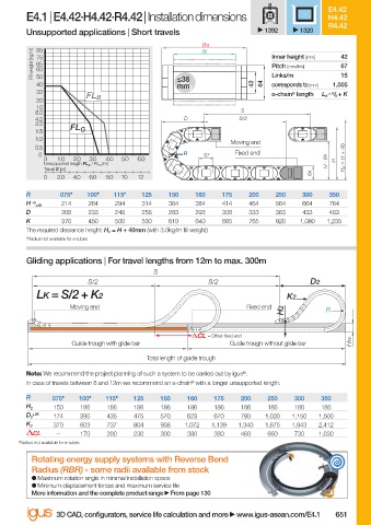
E4.42
                        E4.1 | E4.42·H4.42·R4.42 | Installation dimensions                   H4.42
                                                                                             R4.42
                        Unsupported applications | Short travels               1392    1320
                                                                Ba
                           85
                          Fill weight [kg/m]  75                                Inner height [mm]  42
                                                                Bi
                           65
                                                                                                67
                                                                                Pitch [mm/link]
                           60
                                                                                                15
                           50
                           40                              ≤38              42  64  Links/m   1,005
                                                                                corresponds to [mm]
                                                           mm
                           30                                                   e-chain ®  length   = S / 2  + K
                                      FL B                                                  L K
                           20
                           10
                          8.0                                            S
                          4.0                               D            S/2
                          2.0
                                  FL G
                          1.5
                          1.0
                                                                       Moving end
                          0.5
                           0                                R    67     Fixed end
                            0  1.0  2.0  3.0  4.0  5.0  6.0                                  H - 64  H  H F  = H + 40
                            Unsupported length FL G  / FL B  [m]
                            Travel S [m]
                                                                                         64
                            0  2.0  4.0  6.0  8.0  10  12
                        R       075*  100*  115*   125   150   160   175   200   250   300   350
                        H  -0   214   264    294   314   364   384   414   464   564   664   764
                          +25
                        D       208   233    248   258   283   293   308   333   383   433   483
                        K       370   450    500   530   610   640   685   765   920   1,080  1,235
                        The required clearance height: H F  = H + 40mm (with 3.0kg/m fi ll weight)
                        *Radius not available for e-tubes
                        Gliding applications | For travel lengths from 12m to max. 300m
                                                     S
                                      S/2                         S/2                    D2
                           LK = S/2 + K2                                            K2
                                  Moving end                               Fixed end
                                                                                   H2        R
                                                                  = Off set fi xed end
                                   Guide trough with glide bar         Guide trough without glide bar  HRi
                                                    Total length of guide trough
                        Note: We recommend the project planning of such a system to be carried out by igus ® .
                        In case of travels between 8 and 12m we recommend an e-chain ®  with a longer unsupported length.
                        R     075*  100*  115*   125   150   160   175   200   250   300    350
                        H 2   150    186   186   186   186   186   186   186   186   186    186
                          +25
                        D 2   174    390   435   475   570   623   670   780   1,030  1,150  1,500
                        K 2   370    603   737   804   938  1,072  1,139  1,340  1,675  1,943  2,412
                          CL   –     170   200   230   300   380   380   460   660   730   1,030
                      *Radius not available for e-tubes
                          Rotating energy supply systems with Reverse Bend
                          Radius (RBR) - some radii available from stock
                          ●  Maximum rotation angle in minimal installation space
                          ●  Minimum displacement forces and maximum service life
                          More information and the complete product range   From page 130

                               3D CAD, confi gurators, service life calculation and more   www.igus-asean.com/E4.1  651


                                                                                             05.06.23   18:48
                    10)-ASEAN-E4-1-2022.indd   651
                    10)-ASEAN-E4-1-2022.indd   651                                           05.06.23   18:48