Page 485 - MiSUMi FA Mechanical Components Economy Series
P. 485

Economy Series
          Product Overview                                          Motorized Positioning Stages


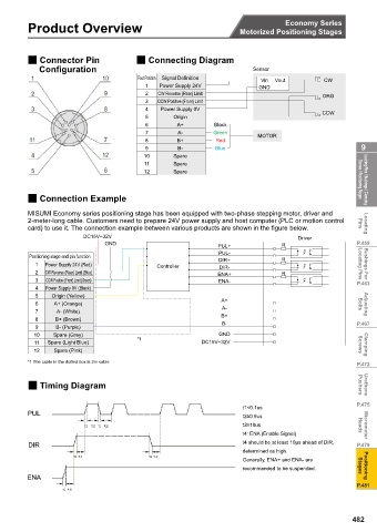
          2 Connector Pin               2 Connecting Diagram
             Configuration                                              Sensor
                                        Foot Position  Signal Definition
                                                                          Vin  Vout        CW
                                          1   Power Supply 24V            GND
                                          2   CW Reverse (Rear) Limit                      ORG
                                          3   CCW Positive (Front) Limit
                                          4    Power Supply 0V
                                                                                           CCW
                                          5       Origin
                                                   A+        Black
                                          7        A-        Green
                                                                         MOTOR
                                          8        B+         Red
                                          9        B-         Blue                                    9
                                          10      Spare
                                          11      Spare
                                          12      Spare                                              Screws / Positioning Stages  Locating Pins / Bushings / Clamping


          2 Connection Example

          0,680, (FRQRP\ VHULHV SRVLWLRQLQJ VWDJH KDV EHHQ HTXLSSHG ZLWK WZR SKDVH VWHSSLQJ PRWRU  GULYHU DQG
          2-meter-long cable. Customers need to prepare 24V power supply and host computer (PLC or motion control   Pins
          card) to use it. The connection example between various products are shown in the figure below.  Locating
                          DC15V~32V                                                 Driver
                               GND                                              R                   P.459
                                                              PUL+
                                                               PUL-
           Positioning stage end pin function
                                                               DIR+             R
            1  Power Supply 24V (Red)         Controller       DIR-                                  Locating Pins  Bushings For
            2  CW Reverse (Rear) Limit (Blue)                 ENA+              R
            3  CCW Positive (Front) Limit (Green)             ENA-                                  P.463
            4  Power Supply 0V (Black)
            5    Origin (Yellow)
                  A+ (Orange)                                  A+                                    Bolts  Adjusting
            7     A- (White)                                   A-
                                                               B+
            8     B+ (Brown)
            9     B- (Purple)                                  B-                                   P.467
            10   Spare (Grey)                                  GND
            11  Spare (Light Blue)      *1                DC15V~32V                                  Screws  Clamping
            12   Spare (Pink)
          *1 The cable in the dotted box is 2m cable
                                                                                                    P.472

          2 Timing Diagram                                                                           Pushers  Urethane


                                                                                                    P.475
                                                                     t1<0.1us
          PUL
                                                                     W •   XV
                                                                     W •  XV                         Heads  Micrometer
                                                                     t4: ENA (Enable Signal)
          DIR                                                        W  VKRXOG EH DW OHDVW   ȝV DKHDG RI ',5    P.479
                                                                     determined as high.
                                                                     *HQHUDOO\  (1$  DQG (1$  DUH
                                                                     recommended to be suspended.    Stages  Positioning
          ENA
                                                                                                    P.481


                                                                                                   482
   480   481   482   483   484   485   486   487   488   489   490