Page 486 - MiSUMi FA Mechanical Components Economy Series
P. 486
Economy Series
Motorized Positioning Stages Product Overview
2 Driver
Two-Phase Part Number Pulse Signal Voltage (V) Power Voltage (V) Output Current (A) Subdivision
Stepping Motor
Driver C-DR42A 5~24 DC15~32 0.1~2.2 200~20000
2 Current Setting 2 Subdivision Setting
Constant Value SW1 SW2 SW3 SW4 Steps/Revolution SW5 SW6 SW7 SW8
Default[0.1A] on on on on Default[200] on on on on
9 0.2A off on on on 1600 off on on on
400
0.3A
on
on
off
on
800
off
on
on
on
Locating Pins / Bushings / Clamping Screws / Positioning Stages 0.6A on on off on 12800 on on off on
on
off
on
on
off
on
0.5A
off
off
3200
on
off
off
on
off
3600
off
on
on
0.7A
off
off
off
off
6400
on
on
0.8A
on
on
off
off
on
off
off
off
off
on
1.0A
1.2A
off
off
2000
off
off
1.3A on on on off 1000 on on on off
on
on
on
on
Locating Pins 1.5A on off on off 4000 on off on off
off
off
on
5000
1.6A
off
off
on
off
off
off
on
off
on
on
off
off
on
7200
1.7A
8000
P.459 1.8A off on off off 10000 off on off off
off
off
off
off
2.0A
on
off
on
off
Bushings For Locating Pins 2.2A off off off off 20000 off off off off
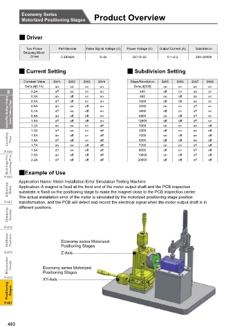
P.463 2Example of Use
Application Name: Motor Installation Error Simulation Testing Machine
Adjusting Bolts Application: A magnet is fixed at the front end of the motor output shaft and the PCB inspection
substrate is fixed on the positioning stage to make the magnet close to the PCB inspection center.
transformation, and the PCB will detect and record the electrical signal when the motor output shaft is in
P.467 The actual installation error of the motor is simulated by the motorized positioning stage position
different positions.
Clamping Screws
P.472
Urethane Pushers Economy series Motorized
Positioning Stages
P.475 Z-Axis
Micrometer Heads Economy series Motorized
P.479 Positioning Stages
XY-Axis
Positioning Stages
P.481
483

