Page 85 - MiSUMi FA Mechanical Components Economy Series
P. 85

1


                Alteration                                                                           Lead Screws / Actuators  Ball Screws /

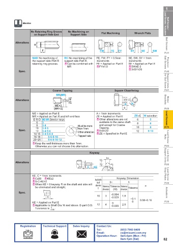
                     No Retaining Ring Groove   No Machining on   Flat Machining   Wrench Flats
                       on Support Side End   Support Side

            Alterations                                                                               Ball Screws
                        R                                             E                 E
                            F                                 FW     FE  FY      SY    SE     SW
                                                                                                     P.31
                      NAR No machining of   RC No machining of the   FE, FW, FY = 0.5mm   SE, SW, SY = 1mm
                      the support side Part R   support side Part R.  increments  increments
                      retaining ring grooves.  &  Can be combined with   FE = Applied on Part E  SE = Applied on Part E  Ball Screws  Precision
                                           MR               &FY≤1.0            &SW≥E-2
                                                                               &3≤SY≤20
              Spec.                                                                                  P.49


                                                                                                     for Ball Screw
                                  Coarse Tapping                       Square Chamfering             P.61
                                                                                                      Support Units
                                    ME(MR)
                                             (D·R)
            Alterations                    E                                    3.2                  Brackets  Motor
                                   ME×2                                      A   W-0.3
                                                                                  -0.1
                                   (MR×2)                                    S                       P.69
                      ME = Applied on Part E                A = 1mm increments
                      MR = Applied on Part R and left end face  ZE = Applied on Part E  ZE=E  W selection  Lead Screws
                       E·R·D ME·MR (Selection range)        &Other alterations are not   6  5
                        6   3                                 available to the same shaft   8  6
                        8   3·4                  Must be more   end except for Coarse
                        10  3·4·5                than 1mm     Tapping.              10      8        P.71
              Spec.     12  3·4·5·6              Other alteration  &5≤A≤20          12     9·10
                       14·15 3·4·5·6·8                      &ZE = Specified in Part E
                       16·18   5·6·8·10          Tapped hole                                         Nuts  Lead Screw
                       20~25   5·6·8·10·12
                      &  Keep the wall thickness more than 1mm.
                        Otherwise you can not choose this alternation.                               P.83
                                                        Keyway

                                                                  b1                                 Support Units   Lead Screw
                                                              1.6
            Alterations
                                                              3.2     t1                             P.86
                                                     E             KE
                                                       C
                                                                   r1
                      KE, C = 1mm increments                                                         Stop Plates  Lead Screw
                      &C≤60    &KE≥2                       Applicable   Keyway Dimension
                      &S-C-KE≥2                             shaft   b1         t1                    P.90
                      &  When KE = 0 keyway R on the shaft end side will   diameter
                        be eliminated and straight.          E  Reference  Tolerance Reference  Tolerance  r1
                                                                       (N9)
                                                                           dimension
                                                                dimension
              Spec.                                                                                   Actuators
                                                             10  3   -0.004  1.8
                               C                                     -0.029
                                                                                 +0.1  0.08~0.16
                      KE = Applied on Part E                          0          0                   P.99
                      &  Applicable to Shaft Dia.16 and above. E-part O.D.   12  4  -0.030  2.5
                        Tolerance is      0  .
                                 -0.05
               Registration  Technical Support  Sales Inquiry  Contact Us:
                                                            Tel:           (60)3 7960 8499
                                                            Email:         cs@misumi.com.my
                                                            Operation Hour:  9am-6pm (Mon - Fri)
                                                                           9am-1pm (Sat)            82
   80   81   82   83   84   85   86   87   88   89   90