Page 83 - MiSUMi FA Mechanical Components Economy Series
P. 83

1


                Alteration                                                                           Lead Screws / Actuators  Ball Screws /

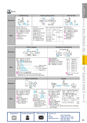
                         Flat Machining            Retaining Ring Groove           Wrench Flats
                              E(R)                  m  AR      AE  m                  E(R)
            Alterations                            R  e            e  E
                                                    n                                                 Ball Screws
                               FE                                  n                  SE
                        FW    (FR)  FY               S(F)   G(T)  F(S)          SY    (SR)   SW
                      FE, FR, FW, FY =    AR, AE =                     + 0.14  Machining  SE, SW, SY =  P.31
                      0.5mm increments    0.1mm increments  R·E e tolerance m 0 n limit  1mm increments
                                                             4
                                                          7
                      FE = Applied on Part E  AR≤S(F)-m-n  8  5  +0.075 0.7  n≥1.2  SE = Applied on Part E
                      FR = Applied on Part R  AE≤S+T-m-n  9  6   0    0.9      SR = Applied on Part R  Ball Screws  Precision
                      &  Applicable to either   (2 segments at right end)  0   &  When E(R)<15
                        E or R            AE≤F+G-m-n     10 9.6  -0.09           SW≥E(R)-2
              Spec.   &  When E(R)≤16     (2 segments at left end)  12 11.5    &  When E(R)≤16       P.49
                        FY≤1.0            Machining limit  14 13.4  0  1.15 n≥1.5   SW≥E(R)-3
                      &3≤FW≤20            AR = Applied on Part R  15 14.3  -0.11  &  3≤SY≤20
                                          AE = Applied on Part E  16 15.2                            for Ball Screw  Support Units
                                                                                                     P.61
                                  Coarse Tapping                     Threaded For Bearing Nut
                                   MR         ME                         For bearing nut             Brackets  Motor
                                                                     M            M  Eh7
            Alterations                                                  R
                               R                  E
                                                                                       Qh7(V)
                                   MR×2  ME×2                                                        P.69
                                                                      BR           BQ
                      MR = Applied on Part R                &BQ,BR≤M×3           Q·R    M×Pitch       Lead Screws
                      ME = Applied on Part E                &BQ,BR≥Pitch×3
                       R·E MR·ME (Selection range)          &BQ,BR≤F,S,T-Pitch×3  8     M8×1.0
                       5·6  3                               BQ = Applied on Part Q  10  M10×1.0      P.71
                       7·8  3·4                             BR = Applied on Part R  12  M12×1.0
                       9·10 3·4·5                Must be more
              Spec.    11·12 3·4·5·6             than 1mm                         14    M14×1.0
                      13~15 3·4·5·6·8            Other alteration                 15    M15×1.0      Nuts  Lead Screw
                        16  3·4·5·6·8·10         Tapped hole                      17    M17×1.0
                      9  R·E=4 is not applicable
                      &  Keep the wall thickness more than 1mm.                  9  Q·R = 7·9·16 is not   P.83
                        Otherwise you can not choose this alternation.            applicable

                                 Square Chamfering                         Keyway                    Support Units   Lead Screw
                                                                               Q(V)
                                         3.2                                                         P.86
            Alterations                                                                  b1
                                                                                       1.6
                                       A  W -0.1                   C  KE(KR)    C  KQ  3.2   t1
                                      S(F)  -0.3                  E(R)                    r1         Stop Plates  Lead Screw
                      W, A = 1mm increments         W       KQ, KE, KR, C = 1mm increments  Applicable   Keyway Dimension
                      ZE = Applied on Part E  ZE=E  1mm     KQ = Applied on Part Q  shaft   b1  t1   P.90
                      ZR = Applied on Part R  ZR=R  increments  KE = Applied on Part E  diameter Reference  Tolerance Reference   r1
                      &  Applicable to either   6~10  5~8   KR = Applied on Part R   Q·E·R dimension  (N9) dimension  Tolerance
                        E or R            11~14    8~10     &  Applicable to   6·7  2 -0.004 1.2
                      &5≤A≤20             15~16    10~14      either Q,E or R                 0.08    Actuators
              Spec.   &ZR = Specified in    (E·R/2)√2≤W     &C≤60           8~10 3  -0.029 1.8  +0.1 ~0.16
                        Part R, ZR>W      &Machining may not   &T-C-KQ≥2    11·12 4     2.5  0
                                                                                    0
                      &ZE = Specified in    be possible in some   &S(F)-C-KE(KR)≥2  -0.030 3.0  0.16  P.99
                        Part E, ZE>W       cases, due to the   &KQ(KE·KR)≥2  13~16 5          ~0.25
                                           relationship between   &  When KQ (KE·KR) = 0,
                                           R (E) and W.       keyway R on the shaft end side will be eliminated
                                                              and straight.

               Registration  Technical Support  Sales Inquiry  Contact Us:
                                                            Tel:           (60)3 7960 8499
                                                            Email:         cs@misumi.com.my
                                                            Operation Hour:  9am-6pm (Mon - Fri)
                                                                           9am-1pm (Sat)            80
   78   79   80   81   82   83   84   85   86   87   88