
Page 188 - MiSUMi FA Mechanical Components Economy Series
P. 188
Economy Series
Technical Calculation For Cable Carriers [Technical Calculation] Cable Carriers
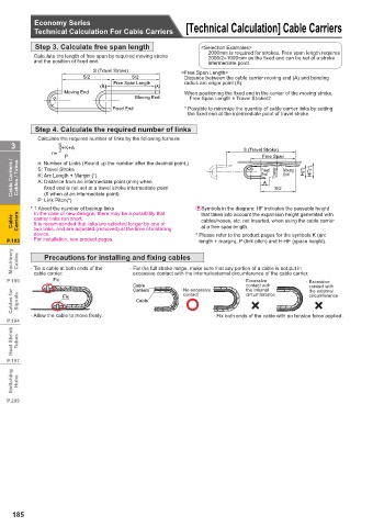
Step 3. Calculate free span length <Selection Examples>
2000mm is required for strokes. Free span length requires
Calculate the length of free span by required moving stroke 2000/2=1000mm as the fi xed end can be set at a stroke
and the position of fi xed end. intermediate point.
S (Travel Stroke) <Free Span Length>
S/2 S/2 Distance between the cable carrier moving end (A) and bending
Free Span Length radius arc origin point (B).
(B) (A)
Moving End When positioning the fi xed end in the center of the moving stroke,
R Moving End Free Span Length = Travel Stroke/2
Fixed End * Possible to minimize the quantity of cable carrier links by setting
the fi xed end at the intermediate point of travel stroke.
Step 4. Calculate the required number of links
Calculate the required number of links by the following formula.
3 S +K+A
2
n: Number of Links (Round up the number after the decimal point.) S (Travel Stroke)
n=
Free Span
P
Cable Carriers / Cables / Tubes S: Travel Stroke R Fixed S/2 Moving H(*) HF(*)
Expansion
End
End
K: Arc Length + Margin (*)
A: Distance from an intermediate point (mm) when
A
fi xed end is not set at a travel stroke intermediate point
(0 when at an intermediate point).
P: Link Pitch(*)
* 1 About the number of backup links & Symbols in the diagram: HF indicates the passable height
· In the case of new designs, there may be a possibility that
that takes into account the expansion height generated with
Cable Carriers · It is recommended that links are selected longer by one or cables/hoses, etc. not inserted, when using the cable carrier
carrier links run short.
at a free span length.
two links, and are adjusted (removed) at the time of installing
device. * Please refer to the product pages for the symbols K (arc
P.183 · For installation, see product pages. length + margin), P (link pitch) and H-HF (space height).
Machinery Cables · Tie a cable at both ends of the · For the full stroke range, make sure that any portion of a cable is not put in
Precautions for installing and fi xing cables
Fix
· Excessive
P.190 cable carrier. excessive contact with the internal/external circumference of the cable carrier. · Excessive
Cable · No excessive contact with contact with
Cables for Signals Fix Cable contact circumference circumference
the internal
Carriers
the external
×
×
· Allow the cable to move freely. · Fix both ends of the cable with no tension force applied.
P.194
Heat Shrink Tubes
P.197
Switching Hubs
P.209
185