Page 554 - MiSUMi FA Mechanical Components Economy Series
P. 554
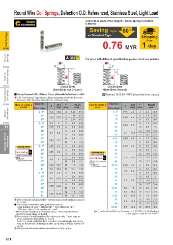
Round Wire Coil Springs, Defection O.D. Referenced, Stainless Steel, Light Load
Coil O.D. D 2mm, Free Height L 5mm, Spring Constant
0.5N/mm
Saving Up to 80 %
Coil Springs vs Standard Type Shipping
from
P.545 0.76 MYR 1 day
Tension Springs For price with different specification, please check our website
D D
d d
P.555 F
Posts For Tension Springs L L F
P.561 (Both Ends Not Ground*) (Both Ends Ground)
Closed Ends
Closed Ends
Torsion Springs/ Disc Springs 2 Spring Constant 0.98~2.9N/mm: Fmax. (Allowable Defl ection)=L × 40% .Material: SUS304-WPB (Imported from Japan)
& O.D. Referenced Type is manufactured giving priority to the outer
diameter, with the inner diameter for reference only.
P.564 How to create a Coil O.D. D Solid F N{kgf} How to create a Coil O.D. D Solid F N{kgf}
-
-
model Free Height L d Length max. max. model Free Height L d Length max. max.
Shock Absorbers 2- 5* 0.26 1.65 2 4 0.98 {0.1} 6- 5* 0.45 2.3 2 4 2.0 {0.2}
0.2
10*
10*
3.9
{0.2}
{0.4}
1.96
0.55
4.4
5.07
15*
P.567 3- 5* 0.3 2 6 2 2.94 {0.3} 15* 6 8 5.9 {0.6}
20
2.0
7.8
{0.8}
{0.2}
11 10* 0.35 3.7 4 3.9 {0.4} 25 0.65 8.5 10 9.8 {1}
15* 0.4 6.6 6 8 5.9 {0.6} 30 0.7 12.6 12 11.8 {1.2}
Springs / Shock Absorbers MISUMI WEB 4- 5* 0.45 11.7 10 11.8 {1.2} 8-10 0.65 4.6 4 6 8 3.9 {0.4}
14
{0.8}
7.8
{1.4}
13.7
35
20*
{1}
25*
9.8
15
5.9
12
30*
{0.6}
{0.2}
2.0
2
{0.8}
8.3
20
0.35
7.8
2.1
0.75
1.Search this keyword
{1}
9.8
coil spring 10* 0.45 5.3 4 6 3.9 {0.4} MISUMI WEB 25 10 11.8 {1.2}
12
15*
30
{0.6}
5.9
2.Select Economy series 1.Search this keyword
Brand 20* 8 7.8 {0.8} coil spring 35 0.8 10.4 14 13.7 {1.4}
MISUMI 0.5 8
Economy series 25* 10 9.8 {1} 2.Select Economy series 40 16 15.7 {1.6}
Brand
30* 0.55 12.7 12 11.8 {1.2} MISUMI 10-10 0.75 4.7 4 3.9 {0.4}
Economy series
40 0.6 19.8 16 15.7 {1.6} 15 6 5.9 {0.6}
0.8 6.2
5- 5* 0.4 2.2 2 2.0 {0.2} 20 8 7.8 {0.8}
10* 4 3.9 {0.4} 25 10 9.8 {1}
0.5 4.75
15* 6 5.9 {0.6} 30 0.9 9.5 12 11.8 {1.2}
20* 8 7.8 {0.8} 35 14 13.7 {1.4}
0.55 6.88
25* 10 9.8 {1} 12-25 1.0 10 10 9.8 {1.0}
30 12 11.8 {1.2} 40 1.2 21.6 16 15.7 {1.6}
0.65 14.95
40 16 15.7 {1.6} 13-20 1.0 8.25 8 7.8 {0.8}
&Both ends are not ground for * marked types; both ends are ground 30 12 11.8 {1.2}
for others. 40 1.1 12.1 16 15.7 {1.6}
* Calculation method of coils (reference value):
Total number of coils = solid length ÷ Wire diameter (d)-1 20-30 1.7 12.8 12 35.3 {3.6}
Effective coils = Total number of coils-2
* The number of coils is a reference value. There may be some kgf (Load)=N/mm (Spring Constant) × 0.101972 × F (Deflection)
variations depending on the lot. Load (kgf) = Load N × 0.101972
& The values of solid length are for reference only. There may be
some variations depending on the lot.
And if it is used under the limit condition of solid length, the spring
may be deformed, or damaged after using only a limited number of
cycles.
& Always use within the allowable deflection Fmax.(mm).
551

