
Page 559 - MiSUMi FA Mechanical Components Economy Series
P. 559
3.3.3 Spring Material Diameter n= Gd 4 f EEEEEEEEEEEEEEEEEEE(25)
The spring material diameter D is calculated by Formula (8) and should 8D 3 (F─F0)
be generally complied with GB/T 1358-2009 series. 4.1.8 Defl ection Energy
3.3.4 Spring Diameter 1 Coil Springs
a) Spring Mean Diameter: U = (F+F0) f EEEEEEEEEEEEEEEEEEEEE(26)
2
D1 + D2
D = 2 EEEEEEEEEEEEEEEEEEEEEE(14) 4.2 Spring Characteristics and Defl ection
b) Spring I.D.: 4.2.1 Spring Characteristics P.545
D1 = D ─ d EEEEEEEEEEEEEEEEEEEEEEE(15) The design calculation is the same as that of cylindrical spiral coil springs.
4.2.2 Test Load
c) Spring O.D.: The design calculation is the same as that of cylindrical spiral coil springs. Springs Tension
D2 = D + d EEEEEEEEEEEEEEEEEEEEEEE(16) 4.2.3 Initial Tension
The spring mean diameter D should be generally complied with the GB/T 1358- The close coil tension spring made of materials that do not need
2009 series, and the deviation value can be selected according to GB/T 1239.2- quenching and annealing forms an axial pressure between the coils, P.555
2009 and GB/T 23934-2015. In order to ensure suffi cient installation space, the which is called the initial tension F0. When the applied load exceeds the
increase in diameter of the spring under load should be considered. initial tension, the spring begins to deform. After coiling and forming,
a) When both ends of the spring are fi xed, from the free height to tightening, the increase springs need to be quenched and annealed have no initial tension.
in the mean diameter is calculated according to the approximate formula (17): The initial tension is calculated according to Formula (27): Tension Springs Posts For
t 2 ─ d 2
Δ D =0.05 D EEEEEEEEEEEEEEEEEEEE (17) F0 = πd 3 τ0 EEEEEEEEEEEEEEEEEEEEEE (27)
8D
b) When the two end faces and the supporting seat can rotate freely and the friction is small, P.561
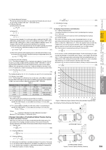
the increase in the mean diameter is calculated according to the approximate formula (18): In the formula, τ0 is the initial tangential stress. For the steel spring, its value
t 2 ─ 0.8td ─ 0.2d 2 can also be selected in the shaded part of Figure 1 according to the winding
Δ D =0.1 D EEEEEEEEEEEEEEEEE (18) ratio C. As the spring generally needs stress relief annealing treatment, the
initial tension of the spring will decrease after treatment. In order to facilitate Disc Springs Torsion Springs/
3.3.5 Number of Coils of Spring
3.3.5.1 The eff ective number of coils of spring is calculated by Formula (10) and manufacturing, it is recommended to take the lower limit value.
should be generally complied with the provisions of GB/T 1358-2009. In order to At the same time, its value can also be calculated by referring to empirical formula (28):
avoid excessive additional forces due to load eccentricity, and to ensure stable τ0 = G EEEEEEEEEEEEEEEEEEEEEEE (28) P.564
stiff ness, there are generally no less than 3 coils and at least no less than 2 coils. 100C
3.3.5.2 The supporting coil n z is related to the structural type of the end coil, and the value of n z is shown in Table 2. 220
3.3.5.3 Total Number of Coils 200 Absorbers Shock
n 1 =n +n z EEEEEEEEEEEEEEEEEEEEEEE (19) 180
The mantissa should be 1/4, 1/2, 3/4 or the whole coil, and 1/2 coil is recommended. P.567
3.3.6 Spring Free Height 160
3.3.6.1 The free height H 0 is aff ected by the end structure, so it is diffi cult to calculate 140 11
the exact value and its approximate value is calculated according to the formula listed
in Table 3, as recommended to follow the provisions of GB/T 1358-2009. 120
Table 3 Initial Torsional Stress IJ0 /MPa 100
Total Number of Coils n 1 Free Height H 0 Pitch t End Structure Type 80
n+1.5 nt+d (H 0-d)/n Absorbers Springs / Shock
n+2 nt+1.5d (H 0-1.5d)/n Both end coils 60
grinding
n+2.5 nt+2d (H 0-2d)/n 40
n+2 nt+3d (H 0-3d)/n Both end coils
n+2.5 nt+3.5d (H 0-3.5 d)/n not grinding 20
3.3.6.2 Solid Height 0 3 4 5 6 7 8 9 10 11 12 13 14 15 16
The solid height of the spring is not specifi ed in principle. C=D/d
a) For a spring with 3/4 coil of end face grinding, when it is necessary to Figure 1 Relationship Diagram Between Winding Ratio and Initial Tangential Stress
specify the solid height, it is calculated according to Formula (20):
H b ≤ n 1d max EEEEEEEEEEEEEEEEEEEEE(20) 4.2.4 Spring Working Drawing (See Figure 2)
(Fs)
b) For a spring without grinding at both ends, when it is necessary to F1 F2
specify the solid height, it is calculated according to Formula (21): F0
H b ≤(n 1+1.5)d max EEEEEEEEEEEEEEEEEEE(21) H1
Where: H2 (Hs)
d max ---Maximum Material Diameter (Material Diameter + (h2)
Maximum Limit Deviation), in millimeter (mm).
4 Design Calculation of Cylindrical Helical Tension Spring
4.1 Basic Calculation Formula
When there is no initial tension, the basic calculation formula of the tension spring is the h1 d
same as that of the coil springs, calculated according to Formula (2) to Formula (11). H0
When there is initial tension, the basic calculation of the tension spring is calculated according to Formula (22) to Formula (26). a) With Initial Tension
4.1.1 Spring Load (Fs)
F2
Gd 4 F1
F = f+F0 EEEEEEEEEEEEEEEEEEEEE(22)
8D 3 n
H1
4.1.2 Spring Defl ection H2
f = 8D 3 n (Hs) (h2)
Gd 4 (F─F0) EEEEEEEEEEEEEEEEEEEE(23)
4.1.3 Spring Stiff ness
Gd 4
F' = F ─ F0 = 8D 3 n EEEEEEEEEEEEEEEEEEE (24)
f
d
4.1.4 The spring Torsional Stress is calculated according to Formula (5) or Formula (6). h1 H0
4.1.5 The spring material diameter is calculated according to Formula (8).
4.1.6 The spring mean diameter is calculated according to Formula (9). b) Without Initial Tension
4.1.7 Eff ective Number of Coils of Spring Figure 2 Tension Spring Working Drawing 556