Page 583 - MiSUMi FA Mechanical Components Economy Series
P. 583

Economy Series
          Quality Assurance                                                    Proximity Sensors


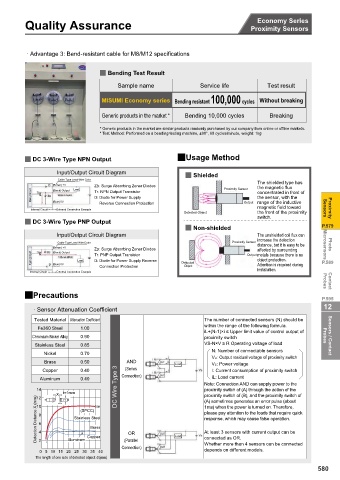
           · Advantage 3: Bend-resistant cable for M8/M12 specifications

                                 2 Bending Test Result

                                      Sample name              Service life         Test result

                                  MISUMI Economy series Bending resistant100,000 cycles Without breaking
                                  Generic products in the market *  Bending 10,000 cycles  Breaking

                                 * Generic products in the market are similar products randomly purchased by our company from online or offline markets.
                                 * Test Method: Performed on a bending testing machine, ±90°, 60 cycles/minute, weight: 1kg


          2 DC 3-Wire Type NPN Output                    2Usage Method
                    Input/Output Circuit Diagram           2 Shielded
                    Cable Type Lead Wire Color
                                                                                 The shielded type has
                   (Brown) +V  Load  ZD: Surge Absorbing Zener Diodes  Proximity Sensor  the magnetic flux
            Main Circuit  (Black) Output  Tr: NPN Output Transistor              concentrated in front of
                                                                                 the sensor, with the
                               D: Diode for Power Supply
                                                                                 range of the inductive
                   (Blue) 0V
                                 Reverse Connection Protection
                                                                             Output
                                                                                 magnetic field toward
            Internal Circuit  External Connection Example                                            Sensors  Proximity
                                                           Detected Object       the front of the proximity
                                                                                 switch.
          2 DC 3-Wire Type PNP Output
                                                           2 Non-shielded                           P.579
                    Input/Output Circuit Diagram                                 The unshielded coil flux can
                                                                                 increase the detection
                    Cable Type Lead Wire Color                           Proximity Sensor  distance, but it is easy to be   Microsensors
                   (Brown) +V                                                                         Photo
                               ZD: Surge Absorbing Zener Diodes                  affected by surrounding
                   (Black) Output
            Main Circuit  Load  Tr: PNP Output Transistor  Detected           Output metals because there is no   P.589
                                                                                 object protection.
                               D: Diode for Power Supply Reverse
                   (Blue) 0V
                                 Connection Protection     Object                Attention is required during
            Internal Circuit  External Connection Example                        installation.       Probes  Contact
          2Precautions                                                                              P.595
                                                                                                     12
             · Sensor Attenuation Coefficient
             Tested Material Attenuation Coefficient             The number of connected sensors (N) should be
              Fe360 Steel  1.00                                  within the range of the following formula.
                                                                 iL+(N-1)×i ” Upper limit value of control output of
            Chromium Nickel Alloy  0.90                          proximity switch                    Probes  Sensors / Contact
             Stainless Steel  0.85                               VS-N×V • R Operating voltage of load
                                                                   N: Number of connectable sensors
                Nickel     0.70
                                                                   VR: Output residual voltage of proximity switch
                Brass      0.50          AND
                                                        Load       VS: Power voltage
                Copper     0.40          (Series                   I: Current consumption of proximity switch
                                                                   iL: Load current
               Aluminum    0.40       Type 3  Connection)        Note: Connection AND can supply power to the
              14                                                 proximity switch of (A) through the action of the
                    X  t=1mm    Iron  Wire  DC                   proximity switch of (B), and the proximity switch of
              Detection Distance X (mm)  8 6 4  Stainless Steel  OR  1ms) when the power is turned on. Therefore,
              12
                       d
                                                                 (A) sometimes generates an error pulse (about
              10
                           (SPCC)
                                                                 please pay attention to the loads that require quick
                                                                 response, which may cause false operation.
                              Brass
                                                                 At least 3 sensors with current output can be
                             Copper
                       Aluminum
              2
                                        (Parallel
                                                                 Whether more than 4 sensors can be connected
                                        Connection)     Load     connected as OR.
               0 510 15 20 25 30 35 40                           depends on different models.
             The length of one side of detected object: d (mm)
                                                                                                   580
   578   579   580   581   582   583   584   585   586   587   588