Page 63 - MiSUMi FA Mechanical Components Economy Series
P. 63

1


                            Screw        Shaft overall   Number  Basic Rated Load  Screw support unit (Sold separately)
              How to create a   Shaft  Lead  length L  Y   of              Axial Twisting            Lead Screws / Actuators  Ball Screws /
                 model                                         C (Dynamic)  C (Static)   Play Direction  Shape
                             O.D.      (1mm increments)  Circuits  kN  kN
                                    05                           4.6  13.1
               MISUMI WEB                                   4
             1.Search this keyword                        turns,                      Square Type
              ball screw c5                               1 row           0.015         % P.63
             2.Select  Economy series  25  10  300~900  L-110    9.7  19.3  or   Right                Ball Screws
             Brand                                                         Less       Round Type
                MISUMI                                                                  % P.67
                 Economy series                            1.8
                                    25                    turns,   6.5  15.9                         P.31
                                                          1 row
           &   The Y dimension must be larger than the full length of the nut         kgf=N×0.101972  Ball Screws  Precision
             How to create                                                          Configure  Clear All
               a model  Step  Search on MISUMI official website  Step   Select  Brand  Brand
                       1      ball screw c5                     2        MISUMI       MISUMI         P.49
                                                                      Economy Series
                             Input the keyword and search on the website
                                                                                       Economy series
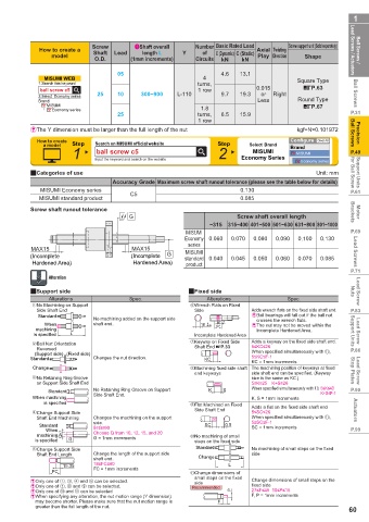
           2Categories of use                                                              Unit: mm  for Ball Screw  Support Units
                                  Accuracy Grade Maximum screw shaft runout tolerance (please see the table below for details)
              MISUMI Economy series                                   0.130                          P.61
                                       C5
              MISUMI standard product                                 0.085
           Screw shaft runout tolerance                                                              Brackets  Motor
                                       G                             Screw shaft overall length
                                                             ~315  315~400 401~500 501~630 631~800 801~1000
                                                       MISUMI                                        P.69
                                                      Economy  0.060  0.070  0.080  0.090  0.100  0.130
                                                       series
           MAX15                        MAX15                                                         Lead Screws
                                                       MISUMI
           (Incomplete                 (Incomplete   G  standard  0.040  0.045  0.050  0.060  0.070  0.085
            Hardened Area)              Hardened Area)  product
                                                                                                     P.71
                Alteration
           2Support side                               2Fixed side                                   Nuts  Lead Screw
                Alterations            Spec.                 Alterations           Spec.
              No Machining on Support                     Wrench Flats on Fixed
             Side Shaft End                              Side            Adds wrench fl ats on the fi xed side shaft end.  P.83
             Standard                                                    &  Ball bearings will fall out if the ball nut
                             No machining added on the support side       crosses the wrench flats.
                                                               10 7
               When          shaft end.                    18     -0.25  37  &  The nut may not be moved within the
                                                             0
             machining                                                    Incomplete Hardened Area.
            is specified  L                              Incomplete Hardened Area                    Support Units   Lead Screw
              Ball Nut Orientation                        Keyway on Fixed Side   Adds a keyway on the fi xed side shaft end.
                                                                         5≤KC≤26
             Reversed                                    Shaft End %P.33                             P.86
            (Support side)  (Fixed side)                                 When specifi ed simultaneously with 2,
           Standard          Changes the nut direction.     KC           5≤KC≤F-1
                                                                         KC = 1mm increments
            Change                                        Machining fi xed side shaft  The machining position of keyways at fi xed
                                                         end keyways     side shaft end can be specifi ed. (Keyway   Stop Plates  Lead Screw
              No Retaining Ring Groove                                   size is the same as KC.)
             on Support Side Shaft End                                   5≤K≤25 K+S≤26
                Standard     No Retaining Ring Groove on Support   K  S  When specifi ed simultaneously with 2,  5≤K≤43  P.90
                                                                                            K+S≤F-1
            When machining   Side Shaft End.                             K, S = 1mm increments
                is specified                              Flat Machined on Fixed
                                                         Side Shaft End  Adds a fl at on the fi xed side shaft end
              Change Support Side                                        5≤SC≤26                      Actuators
             Shaft End Machining  Changes the machining on the support   When specifi ed simultaneously with 2,
                             side.                                       5≤SC≤F-1
              Standard                                      SC    0.5    SC = 1mm increments
                When         5≤G≤60                                                                  P.99
              machining  Qh7  Choose Q from 10, 12, 15, and 20    No machining of small
             is specified  G  G = 1mm increments         steps on the fi xed side
              Change Support Side                        Standard        No machining of small steps on the fi xed
             Shaft End Length  Change the length of the support side   Change  side
                             shaft end.
                    15.35    18≤FC≤60                              L
                 FC          FC = 1mm increments        2 Change dimensions of
                                                         small steps on the fi xed
           & Only one of  ,  ,   and   can be selected.  side            Change dimensions of small steps on the
           & Only one of  ,   and   can be selected.     Recommended     fi xed side
           & Only one of   and 2 can be selected                   P     27≤F≤45  10≤P≤15
           & When specifying any alteration, the nut motion range (Y dimension)   F, P = 1mm increments
             may become shorter. Please make sure that the nut motion range is   F
             greater than the full length of the nut.
                                                                                                    60
   58   59   60   61   62   63   64   65   66   67   68