
Page 967 - MiSUMi FA Mechanical Components Economy Series
P. 967
[Technical Data]
Geometric Tolerance Indications Excerpts from JIS B0021(1984)
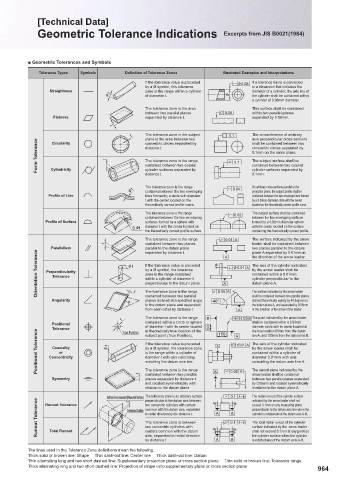
■ Geometric Tolerances and Symbols
Tolerance Types Symbols Defi nition of Tolerance Zones Illustrated Examples and Interpretations
If the tolerance value is preceded П0.08 If a tolerance frame is connected
by a Ø symbol, this tolerance to a dimension that indicates the
Straightness zone is the range within a cylinder diameter of a cylinder, the axis line of
П t of diameter t. П the cylinder shall be contained within
a cylinder of 0.08mm diameter.
The tolerance zone is the area This surface shall be contained
between two parallel planes 0.08 within two parallel planes
Flatness t separated by distance t. separated by 0.08mm.
t The tolerance zone in the subject 0.1 The circumference of arbitrary
axis perpendicular cross sections
plane is the area between two
Form Tolerance t distance t. 0.1 concentric circles separated by
Circularity
shall be contained between two
concentric circles separated by
0.1mm on the same plane.
The subject surface shall be
The tolerance zone is the range
contained between two coaxial
contained between two coaxial
Cylindricity
cylinder surfaces separated by
0.1mm.
distance t. cylinder surfaces separated by
The tolerance zone is the range On arbitrary cross-sections parallel to the
Пt contained between the two enveloping 0.04 projection plane, the subject profi le shall be
Profi le of Line lines formed by a circle with diameter contained between the two envelope lines formed
t with the center located on the by a 0.04mm diameter circle with the center
theoretically correct profi le curve. located on the theoretically correct profi le curve.
The tolerance zone is the range 0.02 The subject surface shall be contained
contained between the two enveloping between the two enveloping surfaces
Profi le of Surface surfaces formed by a sphere with formed by a 0.02mm diameter sphere
S П t diameter t with the center located on with the center located on the surface
the theoretically correct profi le surface. containing the theoretically correct profi le.
The tolerance zone is the range 0.01 A The surface indicated by the arrow
t contained between two planes leader shall be contained between
Parallelism parallel to the datum plane A two planes parallel to the datum
Orientation Tolerance Perpendicularity Пt If the tolerance value is preceded П A П0.01 A The axis of the cylinder indicated
separated by distance t.
plane A separated by 0.01mm in
the direction of the arrow leader.
by the arrow leader shall be
by a Ø symbol, the tolerance
zone is the range contained
contained within a 0.01mm
Tolerance
cylinder perpendicular to the
within a cylinder of diameter t
datum plane A.
perpendicular to the datum plane.
contained between two parallel
shall be contained between two parallel planes
inclined theoretically exactly by 40 degrees to
planes inclined at a specifi ed angle
Angularity t The tolerance zone is the range 40° 0.08 A The surface indicated by the arrow leader
to the datum plane and separated the datum plane A, and separated by 0.08mm
from each other by distance t. A in the direction of the arrow of the leader.
The tolerance zone is the range B
t П0.03 AB The point indicated by the arrow leader
Positional contained within a circle or sphere shall be contained within a 0.03mm
Tolerance True Position of diameter t with its center located 60 100 A diameter circle with its center located at
Positional Tolerance Concentricity П t If the tolerance value is preceded A П0.01 A The axis of the cylinder indicated
at theoretically true location of the
the true location 60mm from the datum
subject point (True Position).
line A, and 100mm from the datum line B.
Coaxiality
by a Ø symbol, the tolerance zone
by the arrow leader shall be
is the range within a cylinder of
contained within a cylinder of
or
diameter 0.01mm with axis
diameter t with axis coinciding
matching the datum axis line.
coinciding the datum axis line A.
contained between two parallel
arrow leader shall be contained
Symmetry t The tolerance zone is the range A 0.08 A The central plane indicated by the
planes separated by distance t
between two parallel planes separated
and located symmetrically with by 0.08mm and located symmetrically
relation to the datum plane. in relation to the datum plane A.
Surface to be measured (Measured Surface) The tolerance zone is an arbitrary surface П 0.1 П AB The radial run-out of the cylinder surface
indicated by the arrow leader shall not
perpendicular to the datum axis between
Runout Tolerance Toleranced Surface common with the datum axis, separated A 0.1 AB perpendicular to the datum axis line when the
t
Runout Tolerance
two concentric cylinders with centers
exceed 0.1mm on any measuring plane
B
in radial direction by the distance t.
cylinder is rotated about the datum axis A-B.
The tolerance zone is between
The total radial runout of the cylinder
two concentric cylinders with
surface indicated by the arrow leader
Total Runout
centers common with the datum
the cylinder surface when the cylinder
axis, separated in radial direction
is rotated about the datum axis A-B.
by distance t. П A B П shall not exceed 0.1mm at any point on
The lines used in the Tolerance Zone defi nitions mean the following.
Thick solid or broken line: Shape Thin dash-dot line: Center line Thick dash-dot line: Datum
Thin alternating long and two short dashed line: Supplementary projection plane or cross section plane Thin solid or broken line: Tolerance range
Thick alternating long and two short dashed line: Projection of shape onto supplementary plane or cross section plane
964