
Page 971 - MiSUMi FA Mechanical Components Economy Series
P. 971
[Technical Data]
Drawing Indications of Surface Texture
Excerpts from JISB0031(1994)
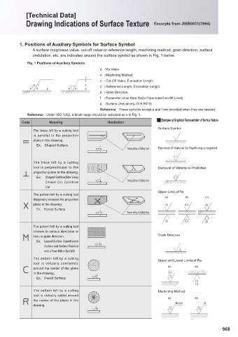
1. Positions of Auxiliary Symbols for Surface Symbol
A surface roughness value, cut-off value or reference length, machining method, grain direction, surface
undulation, etc. are indicated around the surface symbol as shown in Fig. 1 below.
Fig. 1 Positions of Auxiliary Symbols
a : Ra Value
b : Machining Method
b
f c : Cut-Off Value, Evaluation Length
a c c'
e d g e d g c' : Reference Length, Evaluation Length
d : Grain Direction
f : Parameter other than Ra(tp:Parameter/Cut-Off Level)
g : Surface Undulation(JIS B 0610)
Reference These symbols except a and f are provided when they are needed.
Reference Under ISO 1302, a fi nish range should be indicated as e in Fig. 1.
Q Examples of Graphical Representation of Surface Texture
Code Meaning Illustration
Surface Symbol
The trace left by a cutting tool
is parallel to the projection
plane in the drawing.
Ex. Shaped Surface
Trace Left by a Cutting Tool Removal of Material by Machining is required
The trace left by a cutting
tool is perpendicular to the Removal of Material is Prohibited
projection plane in the drawing.
Ex. Shaped Surface(Side View)
Circular Cut, Cylindrical Trace Left by a Cutting Tool
Cut
Upper Limit of Ra
The pattern left by a cutting tool
(a) (b) (c)
diagonally crosses the projection
plane in the drawing. 25 6.3 25
Ex. Honed Surface
Trace Left by a Cutting Tool
25 6.3 25
The pattern left by a cutting tool
crosses in various directions or
has no grain direction. Grain Direction
Ex. Lapped Surface, Superfi nished
Surface and Surface Finished
with a Front Mill or End Mill
The pattern left by a cutting
Upper and Lower Limits of Ra
tool is virtually concentric
(a) (b)
around the center of the plane
in the drawing. 6.3
1.6
Ex. Faced Surface
6.3
1.6
The pattern left by a cutting Machining Method
tool is virtually radial around
(a) (b)
the center of the plane in the
Milled M
drawing.
3.2 3.2
968