Page 263 - IGUS Linear
P. 263

drylin  R shaft guides | igus  testing method                                                                            drylin  R shaft guides | igus  testing method
                                                                                                                                                                                  ®
                   ®
                                                          ®
                                                                                                                                           ®
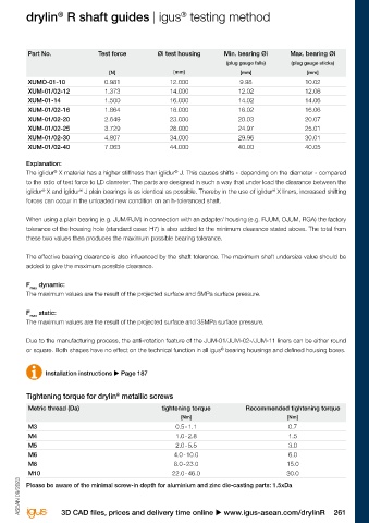
        igus  testing method for measuring the tolerance of drylin  linear plain bearings
                                                                                   ®
              ®
        To ensure the correct function of a drylin  R linear plain bearing, it is necessary to use the bearing with a defined minimum   Part No.        Test force         Øi test housing      Min. bearing Øi       Max. bearing Øi
                                          ®
        oversize (bearing clearance). The quality control of this part is carried out with a plug gauge test. For this purpose, specific force                                                   (plug gauge falls)   (plug gauge sticks)
        is defined with which the plug gauge is loaded when the plain bearing is tested.                                                                   [N]                  [mm]                  [mm]                 [mm]

                                                                                                                                 XUMO-01-10               0.981                12.000                9.98                 10.02
         Part No.                               Test force   Øi test housing  Min. bearing Øi  Max. bearing Øi                   XUM-01/02-12             1.373                14.000                12.02                12.06
                                                                               (plug gauge falls)  (plug gauge sticks)           XUM-01-14                1.500                16.000                14.02                14.06
                                                   [N]            [mm]             [mm]              [mm]                        XUM-01/02-16             1.864                18.000                16.02                16.06
         J / J200 / E7 / A180 / A160UM-01/02-10   0.981          12.000           10.030            10.070                       XUM-01/02-20             2.649                23.000                20.03                20.07
         J / J200 / E7 / A180 / A160UM-01/02-12   1.373          14.000           12.030            12.070                       XUM-01/02-25             3.729                28.000                24.97                25.01
         J / J200 / E7 / A180 / A160UM-01/02-16   1.864          18.000           16.030            16.070                       XUM-01/02-30             4.807                34.000                29.96                30.01
         J / J200 / E7 / A180 / A160UM-01/02-20   2.649          23.000           20.030            20.070                       XUM-01/02-40             7.063                44.000                40.00                40.05
         J / J200 / E7 / A180 / A160UM-01/02-25   3.729          28.000           25.030            25.070
         J / J200 / E7 / A180 / A160UM-01/02-30   4.807          34.000           30.040            30.090                       Explanation:
                                                                                                                                         ®
                                                                                                                                                                                ®
         J / J200 / E7 / A180 / A160UM-01/02-40   7.063          44.000           40.040            40.090                       The iglidur  X material has a higher stiffness than iglidur  J. This causes shifts - depending on the diameter - compared
         J / J200 / E7 / A180 / A160UM-01/02-50   9.810          55.000           50.050            50.150                       to the ratio of test force to LD diameter. The parts are designed in such a way that under load the clearance between the
                                                                                                                                                                                                                ®
                                                                                                                                                  ®
                                                                                                                                      ®
         J / J200 / E7UM-01/02-60                13.047          65.000           60.050            60.150                       iglidur  X and iglidur  J plain bearings is as identical as possible. Thereby in the use of iglidur  X liners, increased shifting
                                                   [N]      [Imperial dimension]  [Imperial dimension]  [Imperial dimension]     forces can occur in the unloaded new condition on an h-toleranced shaft.
         JUI-01-06                                0.981          0.4684           0.3768            0.3776
         JUI-01-08                                1.373          0.5934           0.5016            0.5024                       When using a plain bearing (e.g. JUM/RJM) in connection with an adapter/ housing (e.g. RJUM, OJUM, RGA) the factory
         JUI-01-10                                1.864          0.7184           0.6268            0.6276                       tolerance of the housing hole (standard case: H7) is also added to the minimum clearance stated above. The total from
         JUI-01-12                                2.649          0.8747           0.7516            0.7524                       these two values then produces the maximum possible bearing tolerance.
         JUI-01-16                                3.729          1.1247           1.0016            1.0024
         JUI-01-20                                4.807          1.4058           1.2520            1.2531                       The effective bearing clearance is also influenced by the shaft tolerance. The maximum shaft undersize value should be
         JUI-01-24                                7.063          1.6558           1.5020            1.5031                       added to give the maximum possible clearance.
         JUI-01-32                                9.810          2.1870           2.0024            2.0039
                                                   [N]            [mm]             [mm]              [mm]                        F max  dynamic:
         RJM / RJMP / RJ4JP-01-08                   –            16.000            8.025            8.061                        The maximum values are the result of the projected surface and 5MPa surface pressure.
         RJM / RJMP / RJ4JP-01-10                   –            19.000           10.025            10.061
         RJM / RJMP / RJ4JP-01-12                   –            22.000           12.032            12.075                       F max  static:
         RJM / RJMP / RJ4JP-01-16                   –            26.000           16.032            16.075                       The maximum values are the result of the projected surface and 35MPa surface pressure.
         RJM / RJMP / RJ4JP-01-20                   –            32.000           20.040            20.092
         RJM / RJMP / RJ4JP-01-25                   –            40.000           25.040            25.092                       Due to the manufacturing process, the anti-rotation feature of the JUM-01/JUM-02-/JUM-11 liners can be either round
                                                                                                                                                                                               ®
         RJM / RJMP / RJ4JP-01-30                   –            47.000           30.040            30.092                       or square. Both shapes have no effect on the technical function in all igus  bearing housings and defined housing bores.
         RJM / RJMP-01-40                           –            62.000           40.050            40.112
                                                   [N]      [Imperial dimension]  [Imperial dimension]  [Imperial dimension]
                                                                                                                                       Installation instructions u Page 187
         RJI-01-06                                0.981          0.6250           0.3762            0.3776
         RJI-01-08                                1.373          0.8750           0.5013            0.5030
                                                                                                                                                              ®
         RJI-01-10                                1.864          1.1250           0.6265            0.6282                       Tightening torque for drylin  metallic screws
         RJI-01-12                                2.649          1.2500           0.7516            0.7536                       Metric thread (Da)                         tightening torque          Recommended tightening torque
         RJI-01-16                                3.729          1.5625           1.0035            1.0056                                                                        [Nm]                               [Nm]
         RJI-01-20                                4.807          2.0000           1.2520            1.2544                       M3                                              0.5 - 1.1                           0.7
         RJI-01-24                                7.063          2.3750           1.5020            1.5044                       M4                                              1.0 - 2.8                           1.5
         RJI-01-32                                9.810          3.0000           2.0024            2.0053                       M5                                              2.0 - 5.5                           3.0
                                                   [N]            [mm]             [mm]              [mm]                        M6                                             4.0 - 10.0                           6.0
         RJ260(U)M-02-12                            –            19.000           12.032            12.084                       M8                                             8.0 - 23.0                           15.0
         RJ260(U)M-02-16                            –            24.000           16.032            16.084                       M10                                            22.0 - 46.0                          30.0
         RJ260(U)M-02-20                            –            28.000           20.040            20.100                       Please be aware of the minimal screw-in depth for aluminium and zinc die-casting parts: 1.5xDa
         RJ260(U)M-02-25                            –            35.000           25.040            25.100         ASEAN 09/2023  ASEAN 09/2023


        260 Online tools and more information u www.igus-asean.com/drylinR                                                                  3D CAD files, prices and delivery time online u www.igus-asean.com/drylinR              261
   258   259   260   261   262   263   264   265   266   267   268