
Page 511 - IGUS Linear
P. 511
drylin drive technology | Technical data drylin drive technology | Technical data
®
®
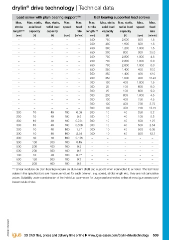
Linear module Lead screw with plain bearing support 121) Ball bearing supported lead screws
Linear module Shaft Ø Thread Pitch Lead screw Carriage length Motor Max. Max. static, Max. static, Max. Max. Max. Max. static, Max. static, Max. Max.
Self-locking connection stroke axial load radial load speed feed stroke axial load radial load speed feed
possible length 120) capacity capacity rate length 120) capacity capacity rate
[mm] [mm] [mm] [N] [N] [rpm] [m/min] [mm] [N] [N] [rpm] [m/min]
TR 12x3 + 100 / 150 + – – – – – 750 750 2,000 500 1.5
TR 12x6P3 + 100 / 150 + – – – – – 750 400 1,600 500 1.5
SAW-1080 10
DS 12x5 + 100 / 150 + – – – – – 750 300 1,200 1,000 1.5
DS 12x25 – 100 / 150 + – – – – – 750 200 800 300 25.0
TR 14x3 + 100 / 150 / 200 + – – – – – 750 700 2,800 1,000 4.5
TR 14x4 + 100 / 150 / 200 + – – – – – 750 700 2,800 1,000 6.0
DS 14x4 + 100 / 150 / 200 + – – – – – 750 700 2,800 1,000 6.0
SAW-1660 16
DS 14x25 – 100 / 150 / 200 + – – – – – 750 350 1,400 400 10.0
DS 14x30 – 100 / 150 / 200 + – – – – – 750 350 1,400 400 12.0
DS 14x40.6 – 100 / 150 / 200 + – – – – – 750 250 1,000 400 16.24
TR 8x1,5 + 38 + – – – – – 300 100 400 1,000 1.5
SLT-0412 5 DS 8x10 – 38 + – – – – – 300 25 100 600 6.0
DS 8x15 – 38 + – – – – – 300 25 100 600 9.0
TR 12x3 + 45 + – – – – – 600 200 800 1,000 4.5
TR 12x6P3 + 45 + – – – – – 600 100 400 750 4.5
SLT-0415 10
DS 12x5 + 45 + – – – – – 600 100 400 750 3.75
DS 12x25 – 45 + – – – – – 600 100 400 750 18.75
M M5x0.8 + 35 + 300 10 40 100 0.08 300 10 40 250 0.2
DS 5x5 – 35 + 250 10 40 100 0.5 250 10 40 100 0.5
DS 6.35x2.54 – 35 + 300 10 40 100 0.254 300 10 40 500 1.27
SLN(V)-27 27
DS 6.35x5.08 – 35 + 300 10 40 100 0.508 300 10 40 500 2.54
DS 6.35x12.7 – 35 + 300 10 40 100 1.27 300 10 40 500 6.35
DS 6.35x25.4 – 35 + 300 10 40 100 2.54 300 10 40 500 12.7
SHTP–01-06 6 M M8x1.25 + 45 + 300 50 50 100 0.125 – – – – –
SHTP–01-10 10 TR 8x1.5 + 26 + 300 100 200 100 0.15 – – – – –
SHTP–01-12 12 TR 10x2 + 55 + 500 200 400 100 0.2 – – – – –
SHTP–02-12 12 TR 10x2 + 55 – 500 200 800 100 0.2 – – – – –
SET-12 12 M M4x0.7 + 30 – 100 10 20 100 0.07 – – – – –
SET-25 25 TR 10x2 + 55 – 500 150 300 100 0.2 – – – – –
SET-30 30 TR 12x3 + 55 – 750 200 400 100 0.3 – – – – –
®
120) When configuring your linear module, we ask that you note the igus specifications for maximum stroke lengths. The 121) Linear modules on plain bearings require an aluminium shaft end support when connected to a motor. The technical
performance and load specifications shown above for all drive units are based exclusively on stroke lengths within the values in the specifications are maximum values for each criterion, e.g. speed, stroke length etc.; they are not cumulative
recommended values. Exceeding these can result in undesirable effects to the function such as increased wear and noise. values. Suitability under consideration of the individual parameters for usage can be checked online at www.igus-asean.com/
Belt or lead screw contact cannot be excluded, and the rated performance and load specifications may not be attainable. linearmodule-finder.
ASEAN 09/2023 ASEAN 09/2023
508 Online tools and more information u www.igus-asean.com/drylin-drivetechnology 3D CAD files, prices and delivery time online u www.igus-asean.com/drylin-drivetechnology 509