
Page 583 - IGUS Linear
P. 583
drylin ZLW-0630 | Technical data drylin ZLW-1040/1080 | Technical data
®
®
1.2 1.0 1.8 1.8
T (a = 1m/s²)
T (a = 1m/s²)
1.0 T (a = 5m/s ) 2 0.8 T (a = 3m/s²) T (a = 0m/s²) 1.6 T (a = 3m/s²) 1.6 T (a = 5m/s²) T (a = 3m/s²)
1.4
1.4
0.8 T (a = 10m/s ) 2 T (a = 3m/s ) 2 0.6 T (a = 10m/s²) T (a = 5m/s²) 1.2 T (a = 10m/s²) T (a = 5m/s²) T (a = 1m/s²) 1.2 T (a = 10m/s²) T (a = 0m/s²)
1.0
1.0
0.6
Drive torque [Nm] 0.4 T (a = 0m/s ) 2 2 Drive torque [Nm] 0.4 Drive torque [Nm] 0.8 T (a = 0m/s²) Drive torque [Nm] 0.8
T (a = 1m/s )
0.6
0.6
0.2
0.2
0.4
0.4
0.0
0 2 4 6 8 0.0 0 1 2 3 4 5 6 7 0.2 1 5 10 15 20 0.2 0 2 4 6 8 10
Load capacity [kg] Load capacity [kg] Load capacity [kg] Load capacity [kg]
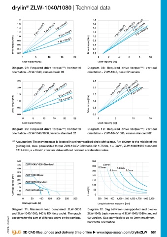
Diagram 01: Required drive torque 138) ; horizontal Diagram 02: Required drive torque 138) ; vertical Diagram 07: Required drive torque 139) ; horizontal Diagram 08: Required drive torque 139) ; vertical
orientation - ZLW-0630, version basic 02 orientation - ZLW-0630, version basic 02 orientation - ZLW-1040, version basic 02 orientation - ZLW-1040, basic 02 version
1.2 1.2 2.5 2.5
T (a = 1m/s²)
T (a = 3m/s²)
T (a = 10m/s²) T (a = 5m/s²) T (a = 5m/s²) T (a = 10m/s²) T (a = 10m/s²) T (a = 0m/s²)
T (a = 5m/s²)
1.0 1.0 T (a = 1m/s²) 2.0 T (a = 5m/s²) T (a = 3m/s²) 2.0 T (a = 3m/s²)
T (a = 1m/s²)
0.8 T (a = 3m/s²) 0.8 T (a = 10m/s²) T (a = 0m/s²) 1.5 T (a = 0m/s²) 1.5
Drive torque [Nm] 0.6 T (a = 1m/s²) Drive torque [Nm] 0.4 Drive torque [Nm] 1.0 Drive torque [Nm] 1.0
0.6
T (a = 0m/s²)
0.5
0.5
0.4
0.2
0.2 0.0 0.0 0.0
1.0 2.5 5 7.5 10 0 2 4 6 8 0 5 10 15 20 25 0 5 10 15
Load capacity [kg] Load capacity [kg] Load capacity [kg] Load capacity [kg]
Diagram 03: Required drive torque 138) ; horizontal Diagram 04: Required drive torque 138) ; vertical Diagram 09: Required drive torque 139) ; horizontal Diagram 10: Required drive torque 139) ; vertical
orientation - ZLW-0630, version standard 02 orientation - ZLW-0630, version standard 02 orientation - ZLW-1040/1080, version standard 02 orientation - ZLW-1040/1080, version standard 02
138) Assumption: The moving mass is located in a circumscribed circle with a max. R = 100mm to the middle of 139) Assumption: The moving mass is located in a circumscribed circle with a max. R = 100mm to the middle of the
the guiding rail, max. permissible torque, ZLW-0630 basic 02: 0.75Nm, a = 0m/s , ZLW-0630 standard 02: guiding rail, max. permissible torque ZLW-1040/1080 basic 02: 1.75Nm, a = 0m/s , ZLW-1040/1080 standard
2
2
1Nm, a = 0m/s , constant drive without nominal acceleration value 02: 2.4Nm, a = 0m/s , constant drive without nominal acceleration value
2
2
5.0 120 5.0 350
4.5 ZLW-1040/1080-Standard 0.3mm 0.5mm 1.0mm 4.5 ZLW-1040/1080-Standard 0.3mm
100 300 0.1mm
4.0 0.1mm 4.0 0.5mm 1.0mm 2.0mm
3.5 ZLW-1040-Basic 80 3.5 ZLW-1040-Basic 250
Carriage speed [m/s] 2.5 ZLW-0630-Standard Load [N] 40 Carriage speed [m/s] 2.5 ZLW-0630-Standard Load [N] 150
200
3.0
3.0
60
2.0
2.0
100
1.5
1.5
20
50
ZLW-0630-Basic
ZLW-0630-Basic
1.0
1.0
0.5
0 50 100 150 200 250 300 0 500 600 700 800 900 1,000 1,100 1,200 0.5 0 50 100 150 200 250 300 0 500 700 900 1,100 1,300 1,500 1,700 1,900 2,100
Carriage loads [N] Length between supports [mm] Carriage loads [N] Length between supports [mm]
Diagram 05: Maximum load compared: ZLW-0630 Diagram 06: Sag between unsupported end blocks Diagram 11: Maximum load compared: ZLW-0630 Diagram 12: Sag between unsupported end blocks
and ZLW-1040/1080, 60% ED (duty cycle). The graph ZLW-0630, basic 02 and standard 02 version. Sag and ZLW-1040/1080, 100% ED (duty cycle). The graph ZLW-1040, basic version and ZLW-1040/1080 standard
accounts for the sum of all forces active on the carriage. permissible up to 2mm maximum. accounts for the sum of all forces active on the carriage. 02 version. Sag permissible up to 2mm maximum -
ASEAN 09/2023 ASEAN 09/2023 horizontal orientation
580 Online tools and more information u www.igus-asean.com/drylinZLW 3D CAD files, prices and delivery time online u www.igus-asean.com/drylinZLW 581