
Page 585 - IGUS Linear
P. 585
drylin ZLW-1660 | Technical data drylin ZLW-20120 | Technical data
®
®
14 14 20 20
M (a = 1m/s²) Nm
M (a = 3m/s²) Nm
M (a = 3m/s²) Nm
M (a = 1m/s²) Nm
M (a = 1m/s²) Nm
M (a = 1m/s²) Nm
12 12 M (a = 3m/s²) Nm 16 M (a = 5m/s²) Nm 16 M (a = 3m/s²) Nm
10 M (a = 5m/s²) Nm 10 M (a = 5m/s²) Nm M (a = 10m/s²) Nm M (a = 0m/s²) Nm M (a = 5m/s²) Nm M (a = 0m/s²) Nm
8 M (a = 10m/s²) Nm M (a = 0m/s²) Nm 5 M (a = 10m/s²) Nm M (a = 0m/s²) Nm 12 12 M (a = 10m/s²) Nm
Drive torque [Nm] 4 Drive torque [Nm] 3 Drive torque [Nm] 8 Drive torque [Nm] 8
4
6
4
4
2
2
0
0 50 100 150 200 250 300 0 0 10 20 30 40 50 0 0 50 100 150 200 250 300 0 0 10 20 30 40 50 60 70 80
Load capacity [kg] Load capacity [kg] Load capacity [kg] Load capacity [kg]
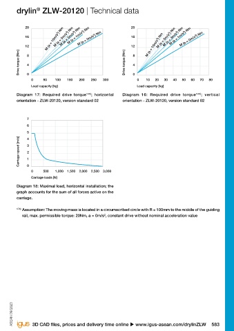
Diagram 13: Required drive torque 140) ; horizontal Diagram 14: Required drive torque 140) ; vertical Diagram 17: Required drive torque 140) ; horizontal Diagram 16: Required drive torque 140) ; vertical
orientation - ZLW-1660, standard 02 version orientation - ZLW-1660, standard 02 version orientation - ZLW-20120, version standard 02 orientation - ZLW-20120, version standard 02
7 7
6 6
5 5
Carriage speed [m/s] 3 Carriage speed [m/s] 3
4
4
2
2
1
1
0
0 500 1,000 1,500 2,000 2,500 0 0 500 1,000 1,500 2,000 2,500 3,000
Carriage loads [N] Carriage loads [N]
Diagram 15: Maximal load, horizontal installation; the Diagram 18: Maximal load, horizontal installation; the
graph accounts for the sum of all forces active on the graph accounts for the sum of all forces active on the
carriage. carriage.
140) Assumption: The moving mass is located in a circumscribed circle with R = 100mm to the middle of the 174) Assumption: The moving mass is located in a circumscribed circle with R = 100mm to the middle of the guiding
guiding rail, max. permissible torque ZLW-1660 standard 02: 10Nm, a = 0m/s , constant drive without nominal rail, max. permissible torque: 20Nm, a = 0m/s , constant drive without nominal acceleration value
2
2
acceleration value
Technical data
Part No. Geometrical moment of inertia Moment of resistance
ly lz Wby Wbz
ZLW-0630 30,391 11,674 1,736 845
ZLW-0660 212,826 17,018 6,448 1,398
ZLW-1040 97,560 54,910 3,902 3,076
ZLW-1080 483,653 486,613 11,515 4,684
ZLW-1660 540,876 4,773,489 14,618 24,586
ASEAN 09/2023 ASEAN 09/2023
582 Online tools and more information u www.igus-asean.com/drylinZLW 3D CAD files, prices and delivery time online u www.igus-asean.com/drylinZLW 583