
Page 595 - IGUS Linear
P. 595
drylin drylin
®
®
®
®
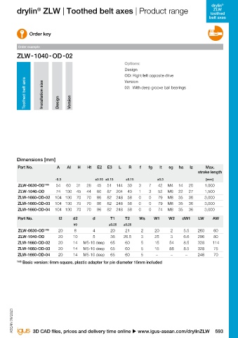
ZLW drylin ZLW | Toothed belt axes | Product range drylin ZLW | Toothed belt axes | Product range ZLW
toothed toothed
belt axes belt axes
Opposite drive toothed belt with angle flange
Order key
Option 04 Order example
W2 Options:
Design
dW1 OD: Right/left opposite drive
W1 Version
lt 02: With deep groove ball bearings
d2
● Quick reverse positioning lz Toothed belt axis
Option 03 Option 02 Al Installation size
● Fast right/left adjustment l2
T1 d Design Version
● Available as standard and basic version
● Incl. angle flange for fixing
T2 AW A
● Individual stroke lengths up to max. 3,000mm
● Radial loads up to 200N
E2
Ws sg E3
Stroke + L
Stroke + LW
Option 04
dW1
Ø d2
f
Dimensions [mm]
W2
Ht W2 Part No. A AI H Ht E2 E3 L R f fg lt sg ha lz Max.
ha
stroke length
dW1 fG W1
W1 -0.3 ±0.15 ±0.15 ±0.15 ±0.3 [mm]
Angle flange alignment: ZLW-0630-OD 109) 54 60 31 28 45 51 144 30 3 7 42 M4 14 20 1,000
lt
d2 ZLW-1040-OD 74 100 45 44 60 87 204 40 1 3 52 M6 22 27 1,500
lz
Option 03 Option 02 Al ZLW-1660-OD-02 104 100 70 70 86 82 248 58 0 0 79 M8 35 36 3,000
l2
T1 d ZLW-1660-OD-03 104 100 70 70 86 82 248 58 0 0 79 M8 35 36 3,000
"02" version
mounted on the side, ZLW ZLW-1660-OD-04 104 100 70 70 86 82 248 58 0 0 74 M8 35 36 3,000
alignment on the edge AW A
T2
Part No. l2 d2 d T1 T2 Ws W1 W2 dW1 LW AW
h9 ±0.25 ±0.25
E2
Ws sg E3 ZLW-0630-OD 109) 20 8 4 20 21 2 20 2 5.5 260 60
Stroke + L
Stroke + LW ZLW-1040-OD 20 10 5 36 26.5 3 25 3 6.6 296 80
Option 04 ZLW-1660-OD-02 20 14 M5-10 deep 65 60 5 15 54 8.5 328 114
Option 04 ZLW-1660-OD-03 20 14 M5-10 deep 65 60 5 15 88 8.5 328 75
dW1
Ø d2
"04" version f ZLW-1660-OD-04 20 14 M5-10 deep 65 60 5 – – – 248 70
mounted horizontally, ZLW W2 109) Basic version: 6mm square, plastic adapter for pin diameter 10mm included
Ht W2
alignment horizontal ha W2
dW1
W1 fG W1
dW1
W1
lt
d2
lt
Option 03 Option 02 lz Al
d2
lz l2
Option 03 Option 02 T1 d Al
"03" version
T1 d l2
mounted on the front T2 AW A
T2 AW A ASEAN 09/2023 ASEAN 09/2023
Ws E2 sg E3
592 Online tools and more information u www.igus-asean.com/drylinZLW Stroke + L 3D CAD files, prices and delivery time online u www.igus-asean.com/drylinZLW 593
E2
E3
Ws sg Stroke + LW
Stroke + L
Stroke + LW
dW1
Ø d2
f
dW1
Ø d2
f
Ht W2
ha
Ht W2
ha fG W1
fG W1