Page 601 - IGUS Linear
P. 601

drylin                                                                                                    drylin
 ®
                                                                                                                ®
                    ®
 ®
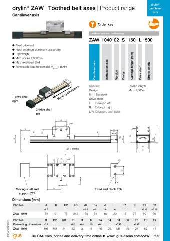
 cantilever   drylin  GRR | Lightweight z-axis | Product range  drylin  ZAW | Toothed belt axes | Product range  cantilever
 axis                                                                                                       axis
 drylin  GRR lightweight z-axis with direct rack drive  Cantilever axis
 ®
                                                                      Order key
 ● 	Made from aluminium and plastic
 ● 	Ideal for linear robots                                     Cantilever axis with ball bearings
 ● 	Direct rack drive
 ®
 ● 	Torsionally rigid due to drylin  AWMR aluminium hollow
 shafts   ● 	Fixed drive unit
 ● 	Lubrication-free and maintenance-free due to drylin  R   ● 	Hard-anodised aluminium axis profile
 ®
 liners   ● 	Lightweight
          ● 	Max. stroke 1,000mm
 Typical application areas:   ● 	Max. axial load 50N
 ● 	Handling  ● 	Permissible load for carriage M y max. : 15Nm                                Carriage length [mm]
 ● 	Sprue pickers                                                   Cantilever axis  Installation size  Drive shaft   Stroke length
 ● 	Room linear robots                                                             Version  Design
 ● 	Lifting equipment
 st
 ● 	Lab automation                                             Options:                    Stroke length
                                          Viewing direction x  S:   Standard
 1  st  d                                                      Design                      Max. 1,000mm
 g  s
 A  4  E  1 drive shaft
 1  d                                                          Drive shaft
 g  s     right
                                                               L:   Drive pin left
 4
 A  E                                                          R:   Drive pin right
 E3                       2 drive shaft
 lt  lw                                    E2                  L/R:  Drive pin, both sides
                          left                     B2
 E3
 lt  lw           ltf                      E2                                    lta                                                              E2
                                                   B2                                                                                                     B2
                               H2                                     fa        E4
 I + stroke  H
 l + Hub
 ha               ltf                                                           lta  B4                                  ltf                                                           lta
 E1  lz  E5  htf                                                                        lta                                                                                  fa        E4
 g2
 2                             H2                                     fa        E4                                                    H2
 E                                                                                                             H
 l + Hub  ha  H                                                                              ha
 w  z                                                                               B4                                                                                                     B4
 h  b1  d  E6  htf                                                                                           E5   htf                                                                         lta
 E1  lz  E5                                                                            lta
 g2
 2  A
 E
 H  6  E
 w  z  E6                                                                                            E6
 h  b1  d                                      LG + stroke
 3  E5                                                                                               A
 f  t  A
 g  g3
 H  6  E
                                              Al
 3  t  E5                                  E3    B
 Technical data  g  g3                 E2     Al                                    B7                                                               Al
 f
 Part No.  Max.  stroke   Transmission  Tooth profile  Weight without   Max. static    E2  E3  B  B7                                          E2  E3    B                                  B7
 length  stroke  load capacity                                                         E7
 [mm]  [mm/rev]  [kg]  axial [N]
 GRR-1280  750  72.26  Module 1  0.86  50                                              E7                                                                                                     E7
                                                                                  l7
 GRR-20120 New  1,000  72.26  Module 1  1.62  75  d      l
            Moving shaft end          lz                           Fixed end block ZTA                                                                                                   l7
                                                                                  l7
 Dimensions [mm]                               d         l                                                                                            d         l
              support ZTF
 Part No.  L  A  H  lw  hw  lz  dz  f  lt  E1  E2  g2  lz                                                                                    lz
 h7       Dimensions [mm]
 GRR-1280  124  100  34  100  62  18  10  2  12  30  25  M4-10  Part No.  A  H  H2  LG  Al  ha  d  l  l7  lz  E2  E3
 GRR-20120 New  202  150  50  172  78  18  10  2  15  30  25  M4-10  -0.3  ±0.3  ±0.1  h9  +1       ±0.15  ±0.15
          ZAW-1040              74     91     75    242    150     74     10     20    15     75     60     60
 Part No.  E3  E4  g3  gt3  E5  E6  g1  sd  st  b1  sd3  st3  D
 h7       Part No.              B     B2     htf   ltf    ff    fa    lta   E4     B4    B7     E5    E6    E7
 GRR-1280  32  41  M5  12  45  20  M5  8  4.5  3  –  –  –  Connecting dimensions  -0.3  ±0.3  ±0.1  h9  ±0.1  ±0.15  ±0.15
 GRR-20120 New  147  80  M8  –  50  20  M5  8  4.5  3  11  6.6  20  ASEAN 09/2023  ASEAN 09/2023  ZAW-1040  M6  M8  44  52  2  5  40  20  M6  M6  26  62  44

 598 More information u www.igus-asean.com/GRR     3D CAD files, prices and delivery time online u www.igus-asean.com/ZAW  599
   596   597   598   599   600   601   602   603   604   605   606