Page 127 - MiSUMi FA Mechanical Components Economy Series
P. 127

Quality Assurance                                                      Economy Series
                                                                                   Linear Guides


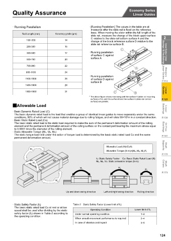
          · Running Parallelism                          · [Running Parallelism] The values in the table are all
                                                          measured after the slide rail is fixed on the reference
                                                          base. When moving the slider within the full length of the
                Rail Length (mm)    $FFXUDF\ JUDGH  ȝP
                                                          slide rail, measure the change of the block upper surface
                                                          C relative to the slide rail bottom surface A and the  2
                   100~200                14
                                                          change of the block reference surface D relative to the
                                                          slide rail reference surface B.
                   200-300                15
                   300-500                17             · Running parallelism                       Bushings / Oil Free Bushings  Linear Guides / Linear
                                                         of surface C against
                                                         surface A
                   500-700                20
                   700-900                22
                  900-1100                24                                                         Linear Guides  Miniature
                                                         · Running parallelism
                  1100-1500               26             of surface D against
                                                         surface B                                  P.113
                  1500-1900               28
                  1900-1960               31                                                         Guides  Linear
                                                         * The above figure shows machining until the surface A (slide rail mounting
                                                         surface) is flat, and the surface B and the surface E (slide rail contact  P.123
                                                         surface) are parallel.
          2Allowable Load

          · Basic Dynamic Rated Load (C)                                                             Bushings  Linear
           The basic dynamic rated load is the load that enables a group of identical linear guides to move separately under the same
           conditions, 90% of which will not cause material damage due to rolling fatigue, and will slide 50×10 m in a constant direction.  P.139
                                                                               3
          · Basic Static Rated Load (Co)
           The basic static rated load is the static load required to make the sum of the permanent deformation amount of the rolling
           element and the permanent deformation amount of the rolling surface on the contact part bearing the maximum stress equal  Bushings  Oil Free
           to 0.0001 times the diameter of the rolling element.
          · Static Allowable Torque (MA,MB,MC)
           The static torque load limit under the action of torque load is determined by the basic static rated load Co and the same  P.161
           permanent deformation amount.

                                                                   $OORZDEOH /RDG  1 ”&R IS          Supports  Shaft
                     M
                      A
                                                                   $OORZDEOH 7RUTXH  1āP ” 0A, MB, MC)/fS
                                                                                                    P.170
                                                             fS: Static Safety Factor  Co: Basic Static Rated Load (N)
                                                             MA, MB, MC: Static allowable torque (N·m)
                       M
                        C                                                                            Collars  Shaft
                                                                          M B
                                                   M A
                                                                                          M C
                                                                                                    P.173
                                    M
                                     B

                                           Up and down swing direction  Left and right swing direction  Rolling direction


          · Static Safety Factor (fS)          Table-2 Static Safety Factor (Lower limit of fS)
           The basic static rated load Co at rest or at low
           speed shall be used after dividing by the static  Operating Condition    Lower limit of fS
           safety factor (fS) shown in Table-2 according to  Under normal operating condition  1~2
           the operating condition.
                                                When smooth movement performance is required  2~4
                                                In case of vibration and impact         3~5


                                                                                                   124
   122   123   124   125   126   127   128   129   130   131   132