Page 139 - MiSUMi FA Mechanical Components Economy Series
P. 139

2Product Dimension
             Nominal                              Block Dimensions (mm)
             model    W     B     B1    C     L1    L2    K1    K2    G     M     T     H2    H3
               15     47    38    4.5   30   39.4  61.4   8    4.85   5.3  M5     6    3.95  3.7
               20     63    53    5.5   40   50.2  77.5  10.25             M6                 6
                                                                                  8     6             2
               25     70    57    6.5   45    58    84   10.7   6     12   M8                 5
               30     90    72    9     52    70   97.4  14.25             M10   8.5   6.5   10.8
             Nominal                    Guide Rail Dimensions (mm)               Guide Rail Fixing Bolt
             model     WR      HR       D       h       d       P         E        Dimensions (mm)   Bushings / Oil Free Bushings  Linear Guides / Linear
               15      15      15      7.5     5.3     4.5                             M4×16
               20      20      17.5    9.5     8.5      6       60    Please refer to   M5×16
                                                                      the calculation
               25      23      22      11       9       7              table below     M6×20
               30      28      26      14       12      9       80                     M8×25
           &Since this product has no surface treatment, please be sure to take anti-rust measures.  Linear Guides  Miniature
           &Dimension tolerance of L Length is ±2 mm.
           &The kit includes 1 block. For additional blocks, please purchase a single block model.
                                                                                                    P.113
           2Allowable Load                             2E Dimension
                 Basic Rated Load Static Allowable Moment  Mass  L  : Guide Rail length
           Nominal                                     M : Guide Rail mounting holes                 Guides  Linear
            model  C (Dynamic)  Co (Static)  MA·MB  MC  Blocks Guide Rails  P : Guide Rail holes pitch
                    kN   kN    kN·m   kN·m  kg     kg/m    L-(M-1)×P
             15    14.7  23.47  0.1   0.12  0.17  1.45  E=    2
             20    27.1  36.68  0.2   0.27  0.4  2.11                                        Number of   P.123
             25    34.9  52.82  0.33  0.42  0.59  3.21  H     24      30       36      42    Mounting
             30    48.5  71.87  0.53  0.66  1.09  4.47                                       Holes M  Bushings  Linear
                                                           100~131  100~139  100~141    -     2
                                                           132~191  140~199  142~201  200~279  3
                Example                                    192~251  200~259  202~261  280~343  4    P.139
                                                            252~311  260~319  262~321  344~423  5
                                                           312~371  320~379  322~381  424~503  6
                                                           372~431  380~439  382~441  504~583  7     Bushings  Oil Free
                                                           432~491  440~499  442~501  584~663  8
                                                           492~551  500~559  502~561  664~743  9    P.161
                                                            552~611  560~619  562~621  744~823  10
                                                           612~671  620~679  622~681  824~903  11
                                                           672~731  680~739  682~741  904~983  12    Supports  Shaft
                                                           732~791  740~799  742~801  984~1063  13
                                                           792~851  800~859  802~861  1064~1143  14
                                                            852~911  860~919  862~921  1144~1223  15  P.170
                                                           912~971  920~979  922~981 1224~1303  16
                                                           972~1031 980~1039 982~1041 1304~1383  17
                                                        L
                                                           1032~1091 1040~1099 1042~1101 1384~1463  18  Collars  Shaft
                                                           1092~1151 1100~1159 1102~1161 1464~1543  19
                                                           1152~1211 1160~1219 1162~1221 1544~1623  20
                                                           1212~1271 1220~1279 1222~1281 1624~1703  21  P.173
                                                           1272~1331 1280~1339 1282~1341 1704~1783  22
                                                           1332~1391 1340~1399 1342~1401 1784~1863  23
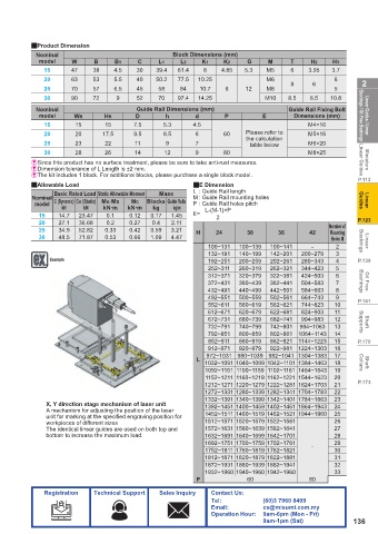
               X, Y direction stage mechanism of laser unit  1392~1451 1400~1459 1402~1461 1864~1943  24
               A mechanism for adjusting the position of the laser
               unit for marking at the specifi ed engraving position for   1452~1511 1460~1519 1462~1521 1944~1960  25
               workpieces of diff erent sizes               1512~1571 1520~1579 1522~1581      26
               The identical linear guides are used on both top and   1572~1631 1580~1639 1582~1641  27
               bottom to increase the maximum load.        1632~1691 1640~1699 1642~1701      28
                                                           1692~1751 1700~1759 1702~1761  -   29
                                                           1752~1811 1760~1819 1762~1821      30
                                                           1812~1871 1820~1879 1822~1881      31
                                                           1872~1931 1880~1939 1882~1941      32
                                                           1932~1960 1940~1960 1942~1960      33
                                                        P             60               80
               Registration  Technical Support  Sales Inquiry  Contact Us:
                                                            Tel:           (60)3 7960 8499
                                                            Email:         cs@misumi.com.my
                                                            Operation Hour:  9am-6pm (Mon - Fri)
                                                                           9am-1pm (Sat)           136
   134   135   136   137   138   139   140   141   142   143   144