Page 55 - MiSUMi FA Mechanical Components Economy Series
P. 55

1


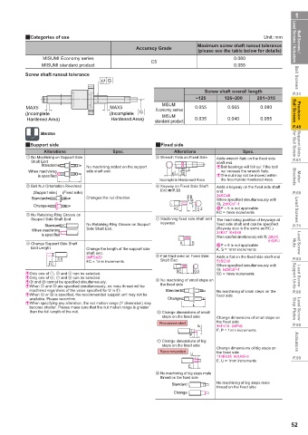
           2Categories of use                                                              Unit: mm
                                                                     Maximum screw shaft runout tolerance   Lead Screws / Actuators  Ball Screws /
                                                Accuracy Grade
                                                                     (please see the table below for details)
                 MISUMI Economy series               C5                          0.080
                 MISUMI standard product                                         0.055
           Screw shaft runout tolerance                                                               Ball Screws
                                       G

                                                                       Screw shaft overall length    P.31
                                                                    ~125      126~200    201~315
                                                         MISUMI
           MAX5                         MAX5           Economy series  0.055   0.065      0.080
           (Incomplete                 (Incomplete   G   MISUMI                                      Ball Screws  Precision
            Hardened Area)              Hardened Area)  standard product  0.035  0.040    0.055
                                                                                                     P.49
                Alteration

           2Support side                               2Fixed side                                   for Ball Screw  Support Units
                 Alterations            Spec.                Alterations            Spec.
              No Machining on Support Side                Wrench Flats on Fixed Side  Adds wrench fl ats on the fi xed side
             Shaft End                                                     shaft end.                P.61
                 Standard       No machining added on the support          &  Ball bearings will fall out if the ball
                                                                5
            When machining      side shaft end.              0     30  5     nut crosses the wrench fl ats.
                is specified                                8-0.2          &  The nut may not be moved within   Brackets  Motor
                          L                             Incomplete Hardened Area  the Incomplete Hardened Area.
              Ball Nut Orientation Reversed               Keyway on Fixed Side Shaft   Adds a keyway on the fi xed side shaft
                                                        End %P.33
              (Support side)  (Fixed side)                                 end.                      P.69
             Standard           Changes the nut direction.        -0.004  -0.029  2≤KC≤8
                                                                           When specifi ed simultaneously with
              Change                                               2        , 2≤KC≤F-1
                                                             KC      1.2   9P = 5 is not applicable   Lead Screws
                                                                           KC = 1mm increments
              No Retaining Ring Groove on
             Support Side Shaft End                       Machining fi xed side shaft end   The machining position of keyways at
                  Standard      No Retaining Ring Groove on Support   keyways  fi xed side shaft end can be specifi ed.   P.71
             When machining     Side Shaft End.                            (Keyway size is the same as KC.)
                                                                           2≤K≤7  K+S≤8
                 is specified                                              When specifi ed simultaneously with  ,  2≤K≤16
                                                                                             K+S≤F-1
              Change Support Side Shaft                        K   S       9P = 5 is not applicable  Nuts  Lead Screw
             End Length         Change the length of the support side      K, S = 1mm increments
                                shaft end.
                                9≤FC≤20                   Flat Machined on Fixed Side   Adds a fl at on the fi xed side shaft end
                      6.8                               Shaft End          5≤SC≤8                    P.83
                   FC           FC = 1mm increments                        When specifi ed simultaneously with
                                                              SC    0.5     , 5≤SC≤F-1
           & Only one of  ,   and   can be selected.                       SC = 1mm increments
           & Only one of  ,   and   can be selected.                                                 Support Units   Lead Screw
           &    and   cannot be specifi ed simultaneously.     No machining of small steps on
           & When 2 and 8 are specifi ed simultaneously, no male thread will be   the fi xed side
             machined regardless of the value specifi ed for U in 2.  Standard  No machining of small steps on the   P.86
           & When 2 or 8 is specifi ed, the recommended support unit may not be   fi xed side
             available. Please reconfi rm.                  Change
           & When specifying any alteration, the nut motion range (Y dimension) may   L
             become shorter. Please make sure that the nut motion range is greater                   Stop Plates
             than the full length of the nut.             Change dimensions of small                  Lead Screw
                                                         steps on the fi xed side  Change dimensions of small steps on
                                                        Recommended        the fi xed side
                                                                      P    9≤F≤18  5≤P≤6             P.90
                                                                           F, P = 1mm increments
                                                                  F
                                                       2  Change dimensions of big                    Actuators
                                                         steps on the fi xed side
                                                                           Change dimensions of big steps on
                                                        Recommended        the fi xed side
                                                                   U
                                                                           11≤E≤35  8≤U≤E-3          P.99
                                                                           E, U = 1mm increments
                                                                  E
                                                       8  No machining of big steps male
                                                        thread on the fi xed side
                                                            Standard       No machining of big steps male
                                                                           thread on the fi xed side
                                                             Change
                                                                                                    52
   50   51   52   53   54   55   56   57   58   59   60