
Page 949 - MiSUMi FA Mechanical Components Economy Series
P. 949
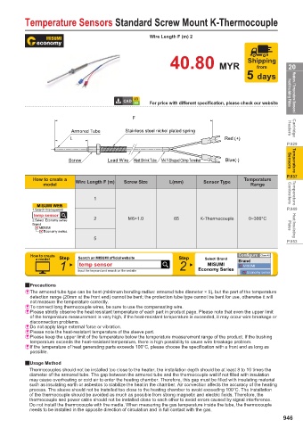
Temperature Sensors Standard Screw Mount K-Thermocouple


                                                      Wire Length F (m) 2


                                                                                       Shipping
                                                             40.80 MYR                    from       20
                                                                                       5 days


                                                      For price with different specification, please check our website  Heat Insulating Plates  Heaters / Temperature Sensors /


                                                F
                           Armored Tube      Stainless steel nickel plated spring                    Heaters  Cartridge
                           L                                                   Red (+)
                                                                                                    P.929


                          Screw        Lead Wire  Heat Shrink Tube  M4 Y-Shaped Crimp Terminal  Blue(-)  Sensors  Temperature

                                                                                                    P.937
              How to create a                                                         Temperature
                 model       Wire Length F (m)  Screw Size  L(mm)       Sensor Type     Range

                                   1                                                                 Controllers  Temperature
               MISUMI WEB
              1.Search this keyword                                                                 P.949
              temp sensor
              2.Select  Economy series  2     M6×1.0          65       K-Thermocouple  0~300°C
              Brand
                MISUMI                                                                               Plates  Heat Insulating
                  Economy series
                                   5
                                                                                                    P.953
             How to create   Search on MISUMI official website                      Configure  Clear All
               a model  Step                                    Step    Select  Brand  Brand
                       1      temp sensor                       2        MISUMI       MISUMI
                                                                      Economy Series
                             Input the keyword and search on the website
                                                                                       Economy series
           2Precautions
           & The armored tube type can be bent (minimum bending radius: armored tube diameter × 5), but the part of the temperature
             detection range (20mm at the front end) cannot be bent; the protection tube type cannot be bent for use, otherwise it will
             not measure the temperature correctly.
           & To connect long thermocouple wires, be sure to use the compensating wire.
           & Please strictly observe the heat resistant temperature of each part in product page. Please note that even the upper limit
             of the temperature measurement is very high, if the heat-resistant temperature is exceeded, it may occur wire breakage or
             disconnection problems.
           & Do not apply large external force or vibration.
           & Please note the heat-resistant temperature of the sleeve part.
           & Please keep the upper limit of the temperature below the temperature measurement range of the product. If the bushing
             temperature exceeds the heat-resistant temperature, there is high possibility to cause wire breakage problem.
           & If the temperature of heat generating parts exceeds 100°C, please choose the specification with a front end as long as
             possible.

           2Usage Method
             Thermocouples should not be installed too close to the heater, the installation depth should be at least 8 to 10 times the
             diameter of the armored tube. The gap between the armored tube and the thermocouple wall if not fi lled with insulation
             may cause overheating or cold air to enter the heating chamber. Therefore, this gap must be fi lled with insulating material
             such as insulating earth or asbestos to stabilize the heat in the chamber. Air convection aff ects the accuracy of the heating
             process. The sleeve should not be installed too close to the heating chamber to avoid exceeding 100°C. The installation
             of the thermocouple should be avoided as much as possible from strong magnetic and electric fi elds. Therefore, the
             thermocouple and power cable should not be installed close to each other to avoid errors caused by signal interference.
             Do not install the thermocouple with the media. When measuring the gas temperature inside the tube, the thermocouple
             needs to be installed in the opposite direction of circulation and in full contact with the gas.
                                                                                                   946