Page 58 - IGUS Bearing
P. 58

iglidur  | Technical data
                    ®
        Wear and shaft materials


        The shaft is, apart from the plain bearing itself, the most   The low wear results of the systems with hard-chromed          15                                                    15
        important parameter in a bearing system. It is in direct   shafts are especially impressive. This very hard, but also
        contact with the bearing, and like the bearing, it is affected   smooth shaft gives excellent results on the wear behaviour   12                                                   12
        by relative motion. The shaft will wear in any case. Modern   with many bearing combinations.The wear of many iglidur         9                                                     9
                                                                                                               ®
        bearing systems however are designed in a way that the   plain bearings is lower on this shaft than on any other
        wear of the shafts is so small that it cannot be detected with   shaft material tested. However, it should be pointed out     6                                                     6
        traditional methods of measurement technology. Shafts can   that because of the low surface roughness, the danger of          3                                                     3
        be distinguished and classified according to their hardness   stick-slip on hard-chromed shafts is especially high.       Wear [µm/km]  M250    W300   J350              A180   Wear [µm/km]  M250    W300   J350              A180
        and according to the surface finish.                  With high-grade steel, a similarly good result is obtained.             0   G      P   J      J3     X  Z   X6  H1            0   G      P   J      J3     X  Z   X6  H1
                                                              Cf53 standard shafts give very good results, too. With                    Diagram 13: Wear with Cf53 shaft,                     Diagram 17: Wear with hard-anodised
        u Coefficient of friction, page 51                    other shaft materials, the wear results vary considerably.                p = 1MPa, v = 0.30m/s, Ra = 0.20μm                    aluminium shaft, p = 1MPa, v = 0.30m/s,
        u Wear resistance, page 54                            For example, in tests with 304 stainless steel shafts at low                                                                    Ra = 0.20μm
                                                              loads, extremely positive results can be found with the right          15                                                    15
        The hardness of the shaft also plays an important role. When   bearing material. It must be said on the other side, that no
        the shafts are less hard, the shaft is worn smooth during   other shaft material shows a bigger variation of wear results    12                                                    12
        the break-in phase. Abrasive points are worn off and the   with different bearing materials. Therefore, the choice of the     9                                                     9
        surface is rebuilt. For some materials, this effect has positive   most suitable bearing material is particularly important with
        influences, and the wear resistance of the polymer bearing    the shaft materials 304 stainless steel and HR carbon steel.    6                                                     6
        increases. In the following graphs, the most common    The test results give only a sample of the existing data. All of       3                                                     3
        shaft materials are listed and the iglidur  materials that   the results shown were made with same loads and speeds.      Wear [µm/km]  M250    W300   J350              A180   Wear [µm/km]  M250    W300   J350              A180
                                            ®
        are best suited are compared. For easier comparison, the                                                                      0   G      P   J      J3     X  Z   X6  H1            0   G      P   J      J3     X  Z   X6  H1
        scaling of the wear axis is the same in all graphs.                                                                             Diagram 14: Wear with 304 stainless steel             Diagram 18: Wear with free cutting steel
                                                                                                                                        shaft, p = 1MPa, v = 0.30m/s, Ra = 0.20μm             shaft, p = 1MPa, v = 0.30m/s, Ra = 0.20μm


                                                                                                                                     15                                                    15

                                                                                                                                     12                                                    12

                                                                                                                                      9 6                                                   9 6

                                                                                                                                  Wear [µm/km]  3  G  M250  P  J  W300  J3  J350  X  Z  X6  H1  A180  Wear [µm/km]  3  G  M250  P  J  W300  J3  J350  X  Z  X6  H1  A180


                                                                                                                                      0
                                                                                                                                        Diagram 15: Wear with HR carbon steel shaft,        0  Diagram 19: Wear with high grade steel shaft,
                                                                                                                                        p = 1MPa, v = 0.30m/s, Ra = 0.20μm                    p = 1MPa, v = 0.30m/s, Ra = 0.20μm


                                                                                                                                     15


                                                                                                                                     12
                                                                                                                                      9 6


                                                                                                                                  Wear [µm/km]  3  G  M250  P  J  W300  J3  J350  X  Z  X6  H1  A180


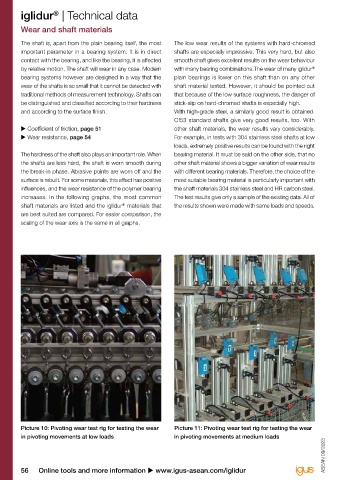
        Picture 10: Pivoting wear test rig for testing the wear   Picture 11: Pivoting wear test rig for testing the wear             0  Diagram 16: Wear with Cf53 hard-chromed
        in pivoting movements at low loads                    in pivoting movements at medium loads                                     shaft, p = 1MPa, v = 0.30m/s, Ra = 0.20μm
                                                                                                                   ASEAN 09/2023  ASEAN 09/2023


        56     Online tools and more information u www.igus-asean.com/iglidur                                                               3D CAD files, prices and delivery times online u www.igus-asean.com/iglidur              57
   53   54   55   56   57   58   59   60   61   62   63