
Page 711 - IGUS Bearing
P. 711
iglidur PRT | Technical data iglidur PRT | Technical data
®
®
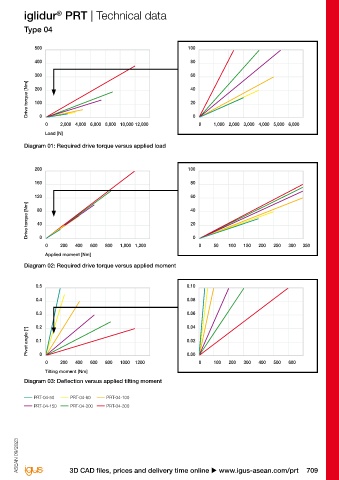
Type 01 Type 04
2,000 100 500 100
1,500 80 400 80
1,000 60 300 60
Drive torque [Nm] 500 40 Drive torque [Nm] 200 40
20
100
20
100
0
0 5,000 10,000 20,000 30,000 50,000 70,000 0 0 1,000 2,000 3,000 4,000 5,000 6,000 0 0 2,000 4,000 6,000 8,000 10,000 12,000 0 0 1,000 2,000 3,000 4,000 5,000 6,000
Load [N] Load [N]
Diagram 01: Required drive torque versus applied load Diagram 01: Required drive torque versus applied load
800 100 200 100
700
80 160 80
600
500 60 120 60
400
Drive torque [Nm] 300 40 Drive torque [Nm] 80 40
200
40
20
20
100
0
0 1,000 2,000 3,000 4,000 0 0 50 100 150 200 250 300 350 0 0 200 400 600 800 1,000 1,200 0 0 50 100 150 200 250 300 350
Applied moment [Nm] Applied moment [Nm]
Diagram 02: Required drive torque versus applied moment Diagram 02: Required drive torque versus applied moment
0.6 0.05 0.5 0.10
0.5 0.04 0.4 0.08
0.4
0.03 0.3 0.06
0.3
0.02 0.2 0.04
Pivot angle [°] 0.1 0.01 Pivot angle [°] 0.1 0.02
0.2
0.0
0 500 1,000 1,500 2,000 2,500 0.00 0 100 200 300 400 500 600 0 0 200 400 600 800 1000 1200 0.00 0 100 200 300 400 500 600
Tilting moment [Nm] Tilting moment [Nm]
Diagram 03: Deflection versus applied tilting moment Diagram 03: Deflection versus applied tilting moment
PRT-01-20 PRT-01-30 PRT-01-50 PRT-01-60 PRT-04-50 PRT-04-60 PRT-04-100
PRT-01-100 PRT-01-150 PRT-01-200 PRT-01-300 PRT-04-150 PRT-04-200 PRT-04-300
All load values assume the PRT is assembled with cap head screws (strength class 8.8) on the outside pitch circle
diameter of the collar clamp. For the assembly (using strength class 8.8 screws) of the PRT, the screws have to be
inserted to a minimum thread depth of 2xd in every hole location in the outer ring. All data can be used for both
lateral and horizontal assembly (including overhead installation). ASEAN 09/2023 ASEAN 09/2023
708 Online tools and more information u www.igus-asean.com/prt 3D CAD files, prices and delivery time online u www.igus-asean.com/prt 709