Page 549 - IGUS Linear
P. 549
drylin                                                                                                    drylin
                                                                                                                ®
 ®
                    ®
 ®
 SLW   drylin  SLW | Linear modules | Product range  drylin  SLW | Linear modules | Product range           SLW
 linear                                                                                                    linear
 modules                                                                                                  modules
 With protected lead screw   Dual action linear system
 ®
 ● 	 drylin  W profile rail as a   ● 	Carriages can be controlled
 protective mechanism  Order key  separately                          Order key
 ● 	 Available with pitches 10x2,   ● 	 Different lead screw pitches can
 10x12, 10x25, 10x50  Order example  be applied                 Order example
 ● 	Low profile design       ● 	 Separate manual adjustment of
 ● 	Available with motor        carriages                                              Options:
                             ● 	Design flexibility                                     BB Ball bearings
                               	Clearance adjustment (optional)
                             ●
 Compact  Ball bearing  Protect  Dimension                         Compact  Double linear   unit  Dimension


                u www.igus-asean.com/drylinSLW
 Select versions and accessories online  Select versions and accessories online
                                                                                                           tk tk
 u www.igus-asean.com/drylinSLW                                     s s                                      ts ts          A A
                                                        l2 l2                      hw  hw
                                                                                                               kt  kt
                                                       ha  ha                                                                        H  H
 tk  A                                                                sg         f f                         tg tg
                                                                      sg
                                                                                                                           sd2
 l2  s  ts                                                      kq  kq                                                     sd2
 hw  f                                                                sk
                                                                      sk
                                                                                         T T
 kt
                                                                         Al Al                 Al Al
 d2  H
                                                              lt lt      E3         d  d      E3           lt lt
                                                                         E3
                                                                                              E3
 tg                                                                              E2  E2                E2  E2  lb lb
 l + Hub
 ha  d  l + stroke  tk
 s             ts               A
 l2  hw
                  kt                                    d2  d2
 ha                                       H                                                                     E1  E1
 tk  A  lt  E3  E2  lt  sg  f  tg                       d2  d2
 l2  s  ts  lb  kq  lb         sd2
 hw  f  sk
 T
 kt                                                                               l + stroke
                                                                                   l + Hub
                                                                                   l + Hub
 Al  Al
 d2  H  E1  lt  E1  E3  d  Technical data
             lt
 tg  E2  E3   lb
 d  T    E2
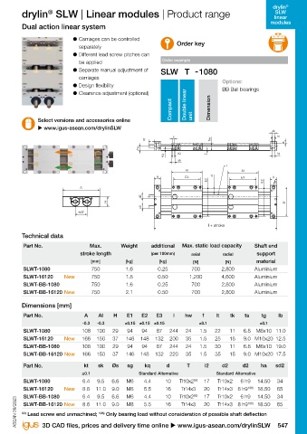
 ha  l + Hub  Part No.              Max.        Weight      additional   Max. static load capacity  Shaft end
                                stroke length               (per 100mm)    axial       radial        support
 A  Al  d2  A
                   E1               [mm]          [kg]         [kg]         [N]         [N]         material
 lt  E3  E2  lt  d2  SLWT-1080      750           1.6         0.25         700         2,800        Aluminium
 lb  lb   SLWT-16120      New       750           1.8         0.50        1,200        4,600        Aluminium
 Technical data
          SLWT-BB-1080              750           1.6         0.25         700         2,800        Aluminium
 Part No.  Max.    Weight  additional   Max. static load capacity  Shaft end   SLWT-BB-16120 New  750  2.1  0.50  700  2,800  Aluminium
 l + Hub
 stroke length  (per 100mm)  axial  radial 97)  support
 E1  E1
 [mm]  [kg]  [kg]  [N]  [N]  material  Dimensions [mm]
 T
 SLW-PT-1040  750  0.75  0.20  700  2,000  Aluminium  Part No.  A  AI  H  E1  E2  E3  l  hw  f  lt  tk  ts  tg  lb
 SLW-BB-PT-1040  750  1.10  0.20  500  2,000  Aluminium
 A  Al  A                        -0.3  -0.3      ±0.15 ±0.15 ±0.15            ±0.1                    ±0.1
 Dimensions [mm]  SLWT-1080      108  100    29   94    94    87   244   24   1.5   22    11   6.8  M8x10 11.0
          SLWT-16120      New    166  150    37   146  148   132   200   35   1.5   25    15   9.0 M10x20 12.5
 Part No.  A  AI  H  E1/E2  E3  l  hw  f  lt  Ib  tk  ts  tg  SLWT-BB-1080  108  100  29  94  94  87  244  24  1.5  30  11  6.8  M8x10 19.0
 -0.3  -0.3  ±0.15  ±0.15  SLWT-BB-16120 New  166  150  37  146  148  132  220  35  1.5  35  15  9.0 M10x20 17.5
 SLW-PT-1040  74  87  29  60  74  131  33.25 3.25  22  11  11  6.8  M8x10
 SLW-BB-PT-1040  74  87  29  60  74  147  33.25 3.25  30  19  11  6.8  M8x10  Part No.  kt  sk  Øs  sg  kq  d  T  l2  d2  d2  ha  sd2
                                 ±0.1                  Standard Alternative          Standard Alternative
 Part No.  kt  d  T  l2  d2  d2 98)  ha
          SLWT-1080              6.4   9.5  6.6   M6     4.4     10    Tr10x2 92)  17  Tr10x2  6 h9  14.50  34
 ±0.1                                                                                            186)
 SLW-PT-1040  6.4  10  Tr10x2  17  Tr10x2  6 h9  14.50  SLWT-16120  New  8.6  11.0  9.0  M8  5.5  16  Tr14x3 92)  20  Tr14x3  8 h9  18.50  65
                                                                                              6 h9
                                       9.5
 SLW-BB-PT-1040  6.4  10  Tr10x2  17  Tr10x2  6 h9  14.50  SLWT-BB-1080  6.4  11.0  6.6  M6  4.4  10  Tr10x2  17  Tr10x2  8 h9 186)  14.50  34
                                                                                                            65
                                                                                                     18.50
                                                                                     Tr14x3
                                            9.0
                                                  M8
          SLWT-BB-16120 New
                                 8.6
                                                                       Tr14x3
                                                                                20
                                                         5.5
                                                                 16
 98)
 97)  Depends on load and rotation speed   Thread/remaining thread visible  ASEAN 09/2023  ASEAN 09/2023  92)  Lead screw end unmachined;  186)  Only bearing load without consideration of possible shaft deflection
 546 Online tools and more information u www.igus-asean.com/drylinSLW       3D CAD files, prices and delivery time online u www.igus-asean.com/drylinSLW  547

