Page 571 - IGUS Linear
P. 571
drylin
                                                                                                                ®
 drylin  SLT | Linear modules | Advantages  drylin  SLT | Linear modules | Product range                   linear
                    ®
 ®
                                                                                                            SLT
                                                                                                          modules
 Flat, lightweight and lubrication-free  With ball bearing supported lead screw
 Lubrication-free linear                             Order key

 modules - drylin  SLT
 ®
 Shaft end supports/                           Order example
 carriages made of
 anodised aluminium  The low profile, the lateral lead screw arrangement
 and a striking design, are just some of the reasons
 ®
 Ball bearing supported    why the drylin  SLT linear module was honoured
 lead screws  with the 2014 IF Award. Technically, the system
 impresses with ball bearing mounted trapezoidal
 Lead screw arrangement    or high helix thread lead screws for motorised or   Adjustable carriage    Lead screw alignment
 left or right of the carriage  manual operation. The basis of the SLT series is   Installation size  Lead screw end  Stroke length in mm
 the drylin  T miniature guide in sizes 12 and 15.                               Lead screw
 ®
 ● 	 Low-profile structure through lateral lead   Type   Design          TWE           Pitch  Thread
 screw arrangement
 Self-locking trapezoidal    ● 	Lubrication-free, corrosion-resistant,   Options:
 thread or fast adjustment    lightweight     Design                    Lead screw         Lead screw end
 with high helix thread  ● 	 Variable pitch   BB:  With ball bearings   S: Steel           G: Threaded end
 ®
 ● 	 Adjustable drylin  T miniature carriage  Lead screw alignment      ES Stainless steel
 drylin  T miniature    ● 	Lead screw arrangement can be selected   R: Right (standard)   Thread
 ®
 carriage with individual   either left or right  L: Left               R: Right
 clearance adjustment
 Typical application areas  A  tk  A         A
 ● 	Format adjustments  kt                        tk               tk
 Lead screws of steel or   ● 	Laboratory and medical technology  H  H  H  kt  d2  kt           d2               d2
 ha
 stainless steel  ● 	Optical equipment  as  tg  f  ha  tg  ha    tg   f                f
                                as               as
                                                                             Al        lt  l2  Al       lt  l2
                                                   lb  lb
 Available in 3-8 days         sg      E3
 Detailed information about delivery time online.
 Hard-anodised drylin  T   d                  E2      E1    T                T
 ®
 miniature guide rail
 Max. +60°C             T                                   d                d     E2      E1        E2      E1
 min. -40°C                                                          sg               sg  lb  lb           lb  lb
                                       Al        lt  l2                     E3                E3
                                                                   l + Hub           l + Hub
                              l + Hub                                               l + stroke
                              l + stroke
 Stroke lengths 300-600mm
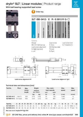
 Hand wheel, position   Lead screw alignment left                           Lead screw alignment right
 indicator and lead screw   More dimensions upon request.
 clamp as accessories    Product finder
 u Page 613  Technical data and dimensions [mm]
 u www.igus-asean.com/slt-productfinder
          Part No.        Pitch      Max.         Weight            Max. static          Max.          Max.
                                    stroke        additional       load capacity         speed         speed
                                    length       (per 100mm)      axial      radial
                                                [kg]    [kg]      [N]         [N]        [1/min]       [m/min]
          SLT-BB-0412    Ds8x15      300       0.15    0.06       25         100         1,000          15
 Can be configured as    SLT-BB-0415  Ds12x25  600  0.40  0.12    100        400         1,000          25
 ready-to-connect linear
 axis with motor and initiators
 u www.igus-asean.com/drylin-automation  In accordance with EC Directive 2011/65 EU (RoHS 2)   Part No.  A  Al  H  E1 E2 E3  l  l2  d2 ha  sg  tk  kt  tg  f  lb  lt  d  T  as
                                                                                          5
                                                                                              20 13 Tr08x1.5 11
                                                                                     2.2
                                                                          6
                                                                               M4
 Restriction (of the use of certain) hazardous substances  SLT-BB-0412 45 38 20 15 20 30 78 15  –  10 M3-7 6.5  4.5 M5–15 2.8 6.5 22 17 Tr12x3 16
 ASEAN 09/2023  ASEAN 09/2023  Also see econ chapter u Page 605
          SLT-BB-0415 58 45 30 19 25 35 89 17 12 15 M3-13 8
 568 Online tools and more information u www.igus-asean.com/drylinSLT      3D CAD files, prices and delivery time online u www.igus-asean.com/drylinSLT  569

