
Page 990 - MiSUMi FA Mechanical Components Economy Series
P. 990
[Technical Data]
Selection of Ball Screws 2
4. Allowable Axial Load
Allowable Axial Load is a load with a safety margin built-in against a shaft bucking load.
Axial load that applies to a ball screw needs to be less than Allowable Maximum Axial Load.
Allowable Axial Load can be obtained by the following formula.
Additionally, approximate Allowable Axial Load can be obtained from Table 1. Allowable Axial Load Graph.
•Allowable Axial Load (P)
n Q EI d 4 Allowable Axial Load Calculation Example
2
4
P 2 αm 2 × 10 (N) Find the Allowable Axial Load for Fig.1
R R
Where: <How to use>
P: Allowable Axial Load (N) · Thread shaft diameter F15, Lead 5
ℓ: Distance between Points of Buckling Load (mm) · Mounting method Fixed - Support
5
E: Young's Modulus (2.06×10 N/mm ) 2 · Distance between Points of Buckling Load ℓ1 820mm
I: Min. Geometrical Moment of Inertia of Across Root Thread Area (mm ) 4 · Screw Shaft Root Diameter d 12.5
Q <Calculations>
I d 4
64 m=10 since the mounting method is Fixed-Supported,
d : Thread Root Diameter (mm) the Allowable Axial Load(P) is,
n,m : Coeffi cient Determined by Method of Screw Support d 4 12.5 4
Pm M10 4 10× M10 4 3630(N)
Method of Screw Support n m R 2 820 2
Support - Support 1 5 Therefore, the allowable axial load will need to be 3630N or less.
Fixed - Support 2 10
Fixed - Fixed 4 19.9 Table.1
Fixed- Free 0.25 1.2
: Safety Factor = 0.5
For higher safety, a higher safety factor should be required.
Distance between Load Acting Points(Buckling Load:Fixed-Fixed) Ɛ1
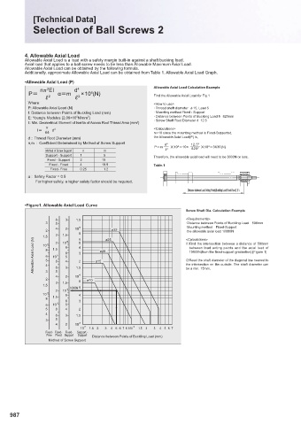
•Figure1. Allowable Axial Load Curve
Screw Shaft Dia. Calculation Example
6 3 1.5 <Requirements>
3 5 ·Distance between Points of Buckling Loadխ500mm
4 2 10 5 ·Mounting methodխFixed-Support
2 ø32 ·the allowable axial load 10000N
3 1.5 8
1.5 4 2 10 5 6 5 ø25 <Calculations>
Allowable Axial Load (N) 8 6 5 4 1.5 8 5 8 6 5 4 4 3 2 ø15 ø20 ΎRead the shaft diameter of the diagonal line nearest to
Find the intersection between a distance of 500mm
10
between load acting points and the axial load of
10000N(from the fi xed-support graduation).[Figure 1]
10
the intersection on the outside. The shaft diameter can
1.5
3
4 6 5 3 2 10 4 be a min. 15mm.
2 ø10
3 1.5 8
1.5 10000N 6
2 10 4
10 3 8 4
8 1.5
6 3
6 10 4 5
5 8 4 2
4
6 3 1.5
3 5
4 2 10 3
10 2 1.5 2 3 4 5 6 7 8 9 10 3 1.5 2 3 4 5 6 7
Fixed- Fixed- Fixed- Support -
Free Fixed Support Support Distance between Points of Buckling Load (mm)
Method of Screw Support
987