Page 994 - MiSUMi FA Mechanical Components Economy Series
P. 994

[Technical Data]
              Selection of Ball Screws 4


           10. Driving Torque                            ΍Constant Speed Torque Exerted on the Motor Output Thread
           This selection provides a guide for selecting ball screw frictional properties and   This is the amount of torque required to drive the output thread against the applied external load, at a constant speed.
           the driving motor.                                 (                                 )
                                                                PL            (3PL-P)     Z1
           10-1.Friction and Effi  ciency                    T1            TP                          (N·cm)
                                                                       2Q˝             3PL               Z2
           When the friction coeffi  cient is O , and lead angle is ı , ball screw's effi  ciency ˝ is
           indicated by the following formulas.           Where:     P≤3PL
                                                           T1  : Driving Torque at Constant Speed (N·cm)
            When rotational force is converted into axial force (Forward Action)
                                                           P   : External Axial Load (N)
                   1-O tan ı                                  PFOMg
            ˝                                             F   : Thrust Reaction Produced in Cutting Force (N)
                 1O/tan ı
                                                           M  : Masses of Table and Work Piece (kg)
            When axial force is converted into rotational force (Reverse Action)  O  : Coeffi  cient of Friction on Sliding Surfaces
                                                           g   : Gravitational Acceleration (9.8m/s ) 2
                     1-O/tan ı                             L   : Ball Screw Lead (cm)
            ˝'
                     1O tan ı                             ˝  : Mechanical Effi  ciency of Ball Screw or Gear
                                                           TP  : Friction Torque Caused by Preloading(N·cm)Referto Formula10-2-Ώ
                                                           PL  : Preload(N)
           10-2.Load Torque                                Z1  : Number of Pinion's Teeth
           The load torque (constant velocity torque) required for the drive power source (motor, etc.) selection is as follows.  Z2  : No. of Gear's Teeth
           ΍Forward Action
           Torque required when converting rotational force into axial force
                                                         ΎAcceleration Torque Exerted on the Motor Output Thread
                      PL                                 This is the amount of torque required to drive the output shaft against the external load during acceleration.
             T           (N·cm)
                    2Q˝
                                                                                2QN
            Where:                                         T2 JM˛  JM             ×10  -3 (N·cm)
              T   : Load Torque (N·cm)                                             60t
                                                                       2
                                                                             Z1
              P  : External Axial Load (N)                 JM J1J4           (J2J3J5J6) (kg·cm ) 2
                                                                    (     )                        
              L   : Ball Screw Lead (cm)                  Where:                   Z2
              ˝  : Ball Screw Effi  ciency (0.9)             T2  : Driving Torque in Acceleration (N·cm)
                                                           ˛  : Motor Thread Angular Acceleration (rad/s ) 2
                                                                                  -1
           ΎReverse Action                                 N   : Motor Thread Rotational Speed (min )
           External axial load when converting axial force into rotational  t   : Acceleration Time (S)
                                                           JM  : Moment of Inertia Exerted on the Motor (kg·cm ) 2
                 2Q  T                                     J1  : Moment of Inertia Exerted on Pinion (kg·cm ) 2
             P            (N)                             J2  : Moment of Inertia Exerted on Gear (kg·cm ) 2

                 ˝ 'L
            Where:                                         J3  : Moment of Inertia Exerted on Ball Screw (kg·cm ) 2
              P   : External Axial Load(N)                 J4  : Moment of Inertia Exerted on Motor's Rotor (kg·cm ) 2
                                                                                     2
              T   : Load Torque(N·cm)                      J5  : Moment of Inertia of Moving Body (kg·cm )
                                                                                   2
              L   : Ball Screw Lead(cm)                    J6  : Moment of Inertia of Coupling (kg·cm )
                                                           M   : Masses of Table and Work Piece (kg)
              ˝ '  : Ball Screw Effi  ciency(0.9)            L   : Ball Screw Lead (cm)
                                                          Moment of inertia exerted on cylinders as screws and cylinders such as Gears
           ΏFriction Torque Caused by Preloading           (Calculation of J1~J4, J6)
                                                              Qγ
           This is a torque generated by preloading. As external loads increase, the preload of   J           D R(kg·cm ) 2
                                                                   4
           the nut is released and therefore the friction torque by preloading also decreases.  32
                                                          Where:
              Under No load                                D   : Cylinder Outer Diameter (cm)
                     PLL                                   R  : Cylinder Length (cm)
              TP K             (N·cm)
                     2 Q                                   γ   : Material Specifi c Gravity
              K0.05(tanı) -  2  1                            γ  7.8×10 (kg/cm )
                                                                         3
                                                                    -3

                                                                     2
                                                                   L
                                                                  (     )
            Where:                                            J5M         (kg·cm ) 2
              PL  : Preload(N)                                            2 Q
              L   : Ball Screw Lead (cm)
              K   : Coeffi  cient of Internal Friction     ΏTotal Torque Exerted on the Motor Output Thread
                                 L
              ı  : Lead Angle  ı≈tan (        )          Overall torque can be obtained by adding results from formulas ΍andΎ.

                            -1
                                QD
                                                                      PL         (3PL-P)   Z1             2 QN
                                                                   (                           )
              D   : Thread Outer Diameter                  TMT1T2         TP                       JM         ×10 (N·cm)
                                                                                          -3
                                                                                           2Q˝            3PL        Z2              60t
           11. Selecting the Driving Motors               Where:
           When selecting a driving motor, it is necessary to satisfy the following   TM  : Total Torque Exerted on the Motor Output Thread(N·cm)
           conditions:                                     T1   : Driving Torque at Constant Speed(N·cm)
           1.Ensure a marginal force suffi  cient to counter the load torque exerted on the motor's output thread.  T2   : Driving Torque at In Acceleration(N·cm)
           2. Enable starting, stopping at prescribed pulse speeds, sufficiently powered to
            counter the moment of inertia exerted on the motor's output thread.  Once you have temporarily found the type of motor you need, check
           3. Obtain the prescribed acceleration and deceleration constants, sufficient to
            counter the moment of inertia exerted on the motor's output thread.  1.eff ective torque,
                                                         2.acceleration constant and
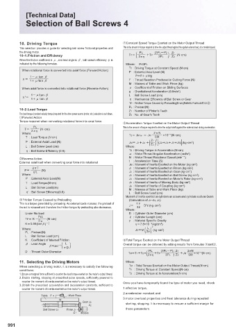
                     Table  F    Work Piece
                                                         3. motor overload properties and heat tolerance during repeated
                             W
                                       Gear J2            starting, stopping. It is necessary to ensure a suffi  cient margin for
                                         Z 2
                                                          these parameters.
                      Ball Screw J3  Pinion J1
                                   Z  1  Motors
      991
   989   990   991   992   993   994   995   996   997   998   999