
Page 998 - MiSUMi FA Mechanical Components Economy Series
P. 998
[Technical Data]
Designing of Chain Drive Mechanism 1
Selection of Power Transmission Effi ciency
The table of transmission performance in this catalog (P. 998) is based on the following conditions.
Q Application Coeffi cient Table
1) The chain drive mechanism is run in an atmosphere with a The power transmission effi ciency table (P.998) is based on minimum
temperature of -10˚C~+60˚C and with no abrasive particles.
2) There is no adverse impact on the mechanism, load variation. The transmitted kW shown in the table should be
such as corrosive gas or high humidity. corrected as follows depending on the actual magnitude of load variation.
3) The two shafts between which power is
transmitted are parallel with each other and Table 1. Application Coeffi cient Table
correctly installed.
4) The recommended lubrication method and oil are used. Impact Prime Motor Type Turbine Internal Combustion Engine
5) The power transmission is subjected to Type Motor With Fluidic Without Fluidic
minimum load variation. Typical Mechanism Mechanism
Belt conveyor with small load
Smooth variation, Chain conveyor,
Centrifugal pump, Centrifugal blower, 1.0 1.0 1.2
Q Power Transmission Coeffi cient for Multiple Chains Transmission General textile machinery, General
On multiple roller chains, the load is not shared evenly between each chain row. Therefore, the machinery with small load variation.
power transmission effi ciency of multiple roller chains cannot be obtained by simply multiplying Transmission Centrifugal compressor, Marine propeller,
the power transmission effi ciency of a single chain by the number of chain rows. The power Conveyor with moderate load variation, Automatic
transmission effi ciency of multiple roller chains should be obtained by multiplying the power with furnace, Drier, Pulverizer, General machine tools, 1.3 1.2 1.4
transmission effi ciency of a single chain by the multiple chain power transmission coeffi cient. Moderate Compressor, General earth-moving machinery,
Impact General paper manufacturing machinery
Table 2. Power Transmission Coeffi cient for Multiple Chains
Press, Crusher, Construction and
Number of Roller Chain Rows Multiple Row Coeffi cient Transmission mining machinery, Vibrator, Oil
2 lines 1.7 with Large well digger, Rubber mixer, Roll, 1.5 1.4 1.7
3 lines 2.5 Impact Rollgang, General machinery with
4 lines 3.3 reverse or impact load
5 lines 3.9
6 lines 4.6
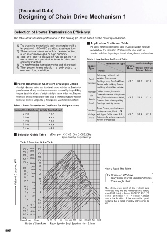
Q Selection Guide Table (Example C-CHE100 / C-CHE20B)
Japanese Standard Type European Standard Type
Table 3. Selection Guide Table
700
1000 500
700 500 300
500 300
300 200 200 CHE240 CHE180
100
Value of Corrected kW 100 70 50 23T 29T 23T 23T 23T 19T 23T 19T 17T 17T CHE160 CHE120 C-CHE80/16B How to Read The Table
CHE200
200
70
100
CHE140
C-CHE100/20B
50
30
70
30
20
50
Ex. Corrected kW=5kW
C-CHE60/12B
20
30
Rotary Speed of Small Sprockets=300r/min
10
17T
20
C-CHE40/09B
When single chain
10 10 7 7 5 23T 23T 23T 17T 17T C-CHE50/10B C-CHE35/06B The intersection point of the vertical axis
7 5 3 13T 23T 13T (corrected kW) and the horizontal axis (rotary
5 3 2 23T 17T 13T C-CHE25 speed 300r/min) is below C-CHE60 23T (23
3 2 23T toothed) and above 17T (17 toothed) A closer
1 17T 13T look at the location of the intersection point
2 0.7 23T 23T
1 0.5 17T indicates that it most probably corresponds to
19T.
1 0.7 30T 17T 13T
0.7 0.5 0.3
0.5 0.3 0.2
0.3 0.2
0.2 0.1
3 lines 2 lines 1 line 20 30 50 100 200 300 500 1000 20003000 5000 10000
Number of Chain Rows Rotary Speed of Small Sprockets min –1 ʨr/minʩ
995