
Page 997 - MiSUMi FA Mechanical Components Economy Series
P. 997
[Technical Data]
Toothed Pulleys Excerpts from JIS B 1856(1993)
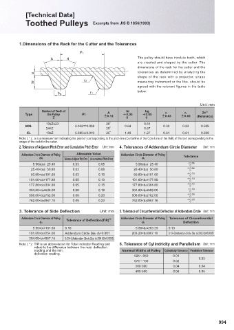
1.Dimensions of the Rack for the Cutter and the Tolerances
Pt
A A The pulley should have involute tooth, which
are created and shaped by the cutter. The
dimensions of the rack for the cutter and the
tolerances as determined by analyzing the
a
shape of the rack with a projector, shape
hr r2 measuring instrument or the like, should be
agreed with the relevant figures in the table
below.
b g r1
Unit: mm
Number of Teeth of hr bg 2a (1)
Type the Pulley Pt A 0.05 0.05 r1 r2
Z Ú0.12 0 0 Ú0.03 Ú0.03 (Reference)
10≤Z≤23 28B 0.61
MXL 2.032Ú0.008 0.64 0.30 0.23 0.508
24≤Z 20B 0.67
XL 10≤Z 5.080Ú0.010 25B 1.40 1.27 0.61 0.61 0.508
1
Note ( ) : a is a measurement indicating the position corresponding to the pitch line (Centerline of the Core Line of the Belt) of the belt corresponding to the
shape of the rack for the cutter.
2. Tolerance of Adjacent Pitch Error and Cumulative Pitch Error Unit: mm 4. Tolerances of Addendum Circle Diameter Unit: mm
Addendum Circle Diameter of Pulley Allowable Value Addendum Circle Diameter of Pulley Tolerance
d0 Tolerance of Adjacent Pitch Error Accumulated Pitch Error d0
5.96≤d0≤ 25.40 0.03 0.05 5.96≤d0≤ 25.40 0.05
0
25.40<d0≤ 50.80 0.03 0.08 25.40<d0≤ 50.80 0.08
0
50.80<d0≤101.60 0.03 0.10 50.80<d0≤101.60 0.10
0
101.60<d0≤177.80 0.05 0.13 101.60<d0≤177.80 0.13
0
177.80<d0≤304.80 0.05 0.15 177.80<d0≤304.80 0.15
0
304.80<d0≤508.00 0.08 0.18 304.80<d0≤508.00 0.18
0
508.00<d0≤762.00 0.08 0.20 508.00<d0≤762.00 0.20
0
762.00<d0≤967.16 0.08 0.23 762.00<d0≤967.16 0.23
0
3. Tolerance of Side Defl ection Unit: mm 5. Tolerance of Circumferential Defl ection of Addendum Circle Unit: mm
Addendum Circle Diameter of Pulley ( 2 ) Addendum Circle Diameter of Pulley Tolerance of Circumferential
Tolerance of Defl ection(TIR)
d0 d0 Defl ection
5.96≤d0≤101.60 0.10 5.96≤d0≤203.20 0.13
101.60<d0≤254.00 Addendum Circle Dia. d0×0.001 203.20<d0≤967.16 0.13+ց(Addendum Circle Dia. d0-203.20)×0.0005ւ
254.00<d0≤967.16 0.25+ց(Addendum Circle Dia. d0-254.00)×0.0005ւ
Note ( ) : TIR is an abbreviation for Total Indicator Reading and 6. Tolerance of Cylindricity and Parallelism Unit: mm
2
refers to the diff erence between the max. defl ection
reading and the min. Nominal Widths of Pulley Cylindricity Tolerance Parallelism Tolerance
defl ection reading.
025։050 0.01 0.03
075։150 0.02
200·300 0.04 0.04
400·500 0.06 0.05
994