
Page 999 - MiSUMi FA Mechanical Components Economy Series
P. 999
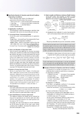
Q Specifi cation Selection for Operation under Normal Conditions 8. Chain Length and Distance between Shaft Centers
1.Operating Conditions Once the chain, the number of teeth on both
sprockets, and the inter-shaft distance are available,
When selecting roller chains, the following 7 determine the number of chain links as follows.
parameters should be taken into account. Lp(No. of links) Lp: Chain Length Expressed in Number
1. Machine to be used 5. Diameter and Rotary Speed of High-Speed Shaft of Links
2. Impact Type 6. Diameter and Rotary Speed of Low-Speed Shaft N1 : Number of Large Sprocket Teeth
3. Prime Motor Type 7. Inter-Shaft Distance N 1 N2 N2 : Number of Small Sprocket Teeth
4. Power Transmission(kW) Cp: Distance between Shaft Centers
Expressed in Number of Links
2. Application Coeffi cient Cp(No.of links) π : ≈3.14
Select the application coeffi cient from the application table(Table 1) that
is appropriate for the machine to be driven and the prime motor type. (1) Calculating the chain length (when the number of sprocket teeth N1
and N2 and the distance between shaft centers Cp are available)
3. Corrected Power Transmission(kW)
Correct the power transmission(kW)using the application N1N2 2
2 Q
coeffi cient. N1N2 ( )
• Single Chain…Corrected Power Transmission(kW)=Power Lp 2 2Cp Cp
Transmission(kW)×Application Coeffi cient
• Multiple Chains…Select the appropriate coeffi cient from the *Round up decimals of Lp to the next whole number.
table multiple-chain power transmission coeffi cients(Table 2). Generally, when the chain length number of chain links obtained is an odd number,
Power Transmission(kW)×Application Coefficient
Corrected Power Transmission(kW)= this should be raised to the next even number. When the inter-shaft distance
Multiple Row Coefficient
demands the chain length to be an odd number, an off set link needs to be used.
4. Chain and Number of Sprocket Teeth However, it should be avoided and an even number should be used as much as
Using the selection guide table(Table 3)or the power transmission possible by adjusting the number of sprocket teeth or the inter-shaft distance.
effi ciency tables, select the chain and the number of small sprocket teeth (2) Calculating the distance between shaft centers (when the number
that satisfy the rotary speed of the high-speed shaft and the corrected of sprocket teeth N1,and N2 as the chain length Lp are available)
power transmission(kW). The chain pitch should be as small as possible,
8
1
as long as the required power transmission efficiency is achieved. Cp 8 2 Q 2 (N1N2) 2
2LpN1N2 (2LpN1N2)
This should minimize noise and ensure smooth transmission of power.
(If a single chain does not provide the required power transmission
effi ciency, use multiple chains instead. If the installation space requires The pitch number obtained by the chain length formula is, in most cases, only approximate
that the inter-shaft distance as well as the outer diameter of sprocket be and not in exact agreement with a given inter-shaft distance. Therefore, it will be necessary to
minimized, use small-pitch multiple chains.)There should be a minimum calculate the exact distance between the shaft centers based on the required overall length.
wrap angle of 120˚ between the small sprocket and the chain.
Q Example of Selection for Operation under Normal Conditions
5. Number of Large Sprocket Teeth The following is an example of selection when a 3.7 kW
Number of Large Sprocket Teeth = Number of Small Sprocket 1,000r/min electric (motor) is used to drive a compressor.
Teeth × Speed Ratio Once the number of small sprocket teeth is [1] Operating Conditions
determined, multiplying this by the speed ratio provides the number 1) Machine to be used ········ Compressor,10 hours operation
of large sprocket teeth. Generally, the appropriate number of small 2) Impact Type ··········· Smooth Transmission
sprocket teeth is 17 or greater, or 21 or greater for high-speed 3) Prime Motor Type ···· Electric Motor
operation, or 12 or greater for low speed operation. The number of 4) Power Transmission 3.7kW
large sprocket teeth should be 120 or less.Select the sprocket with 5) Rotary Speed ········· 1,000r/min
as great a number of teeth as possible for a speed ratio of 1:1 or 2:1. [2] Application Coeffi cient
The speed ratio should normally be 1:7 or less, and ideally 1:5.
From Table 1, an application coeffi cient of 1.2 is selected.
6. Shaft Diameter [3] Corrected Power Transmission(kW)
Ensure that the small sprocket selected as above is compatible with the diameter Corrected Power Transmission(kW)Power Transmission(kW)×Application Coeffi cien
of the existing shaft on which it is to be installed. Refer to the specifi cation table 3.7kW1.24.44kW
on this page. When the shaft diameter is too large for the bore in the sprocket, [4] Chain and Number of Sprocket Teeth
select another sprocket with a greater number of teeth or a larger chain. Searching the selection guide table(Table 3) for a
7. Inter-shaft Distance between Sprockets combination of 1,000r/min and 4.44kW provides a
The distance between the shafts can be reduced as C-CHE40 chain and 17T sprocket.
long as the sprockets do not interfere with each other On the power transmission effi ciency table for the
and the wrap angle between the small sprocket and C-CHE40 chain, a combination of 13T and
the chain is 120˚ or more. 1,000r/min provides a power transmission effi ciency
Generally, the inter-shaft distance should preferably of 4.09 kW, which does not meet the required 4.44
be 30~50 times the pitch of the chain used. Under kW. Therefore, 19T, which achieves 4.6 kW, should
pulsating load conditions, decrease the distance to 20 be selected to meet the requirement.
times the chain pitch or less. Results:The C-CHE40 chain should be selected.
Number of Small Sprocket Teeth=19T
996