
Page 995 - MiSUMi FA Mechanical Components Economy Series
P. 995
[Technical Data]
Selection of Conveyor Timing Belts
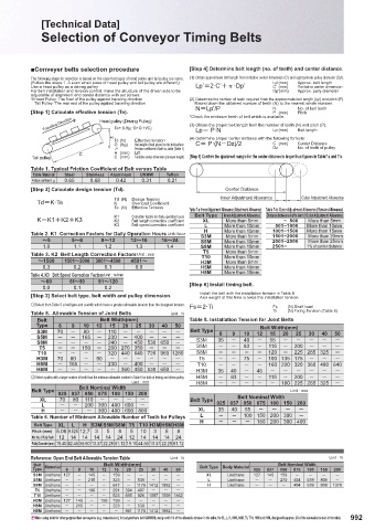
■Conveyer belts selection procedure [Step 4] Determine belt length (no. of teeth) and center distance.
The following steps for selection is based on the case that sizes of head pulley and tail pulley are same. (1) Obtain approximate belt length from tentative center dimension (C') and approximate pulley diameter (Dp').
(Follow the steps 1 -3 even when sizes of head pulley and tail pulley are diff erent) Lp' (mm) Approx. belt length
Use a head pulley as a driving pulley. Lp’2·C’Q·Dp’ C' (mm) Tentative center dimension
For belt installation and tension control, make the structure of the driven side to be Dp'(mm) Approx. pully diameter
adjustable of alignment and center distance with set screws.
˟ Head Pulley: The front of the pulley against traveling direction (2) Determine the number of teeth required from the approximate belt length (Lp') and pitch (P).
Tail Pulley: The rear end of the pulley against traveling direction Round down the obtained number of teeth (N) to the nearest whole number.
NLp’/P N No. of belt teeth
[Step 1] Calculate eff ective tension (Te). *Check the minimum teeth of belt which is available. Pitch
(mm)
P
Traveling Direction Head pulley (Driving Pulley) (3) Obtain the proper belt length from the number of teeth (N) and pitch (P).
Te= 9.8(μ·G+G·H/C)
Lp P·N
Belt length
Lp (mm)
H (4) Determine proper center distance with the following formula:
Te (N) Eff ective tension
G (Kg) Net weight of load placed on the belt surface C P·(NDz)/2 C (mm) Center Distance
O Friction coeffi cient of belt vs. table (Table 1) Dz No. of teeth of pulley
C H (mm) Lift
Tail pulley C (mm) Tentative center dimension (conveyor length) [Step 5] Confi rm the ajustment margin for the center distance is larger than fi gures in Table7-a and 7-b.
Table 1. Typical Friction Coeffi cient of Belt versus Table
Table Material Steel Stainless Aluminium UHMW Tefl on
Friction coeffi cient: O 0.65 0.68 0.42 0.31 0.21
[Step 2] Calculate design tension (Td). Center Distance
Td (N) Design Tension Inner Adjustment Allowance Outer Adjustment Allowance
TdK·Te K Overload Coeffi cient
Te (N) Eff ective Tension
Table 7-a: Inner Adjustment Allowance (Attachment Allowance) Table 7-b: Outer Adjustment Allowance (Tension Allowance)
K1 Correction factors for daily operation hours Belt Type Inner Adjustment Allowance Distance between shafts (mm) Outer Adjustment Allowance
KK1K2K3 K2 Belt length correction coeffi cient XL More than 5mm ~ 500 More than 5mm
K3 Belt speed correction coeffi cient L More than 10mm 501~1000 More than 10mm
H More than 15mm 1001~1500 More than 15mm
Table 2. K1 Correction Factors for Daily Operation Hours Unit: hour S3M More than 5mm 1501~2000 More than 20mm
։5 5։8 8։12 12։16 16։24 S5M More than 10mm 2001~2500 More than 25mm
1.0 1.1 1.2 1.3 1.4 S8M More than 15mm 2501~ 1% of center distance
T5 More than 5mm
Table 3. K2 Belt Length Correction Factors Unit : mm T10 More than 10mm
։1500 1501։3000 3001։4500 4501։ H3M More than 5mm
0.3 0.2 0.1 0.0 H5M More than 10mm
H8M More than 15mm
Table 4. K3 Belt Speed Correction Factors Unit : m/min
։60 61։90 91։120 [Step 6] Install timing belt.
0.0 0.1 0.2
Install the belt with the installation tension in Table 8.
[Step 3] Select belt type, belt width and pulley dimension. Axis weight at this time is twice the installation tension.
Select from Table 5 a belt type and a width which have a greater allowable tension than the designed tension. Fs2·Ti Fs (N) Shaft load
Table 5. Allowable Tension of Joint Belts Unit : N Ti (N) Fixing Tension (Table 8)
Belt Belt Width(mm) Table 8. Installation Tension for Joint Belts
Type 6 9 10 12 15 20 25 30 40 50 Belt Width(mm)
S3M 70 80 110 Belt Type 6 9 10 12 15 20 25 30 40 50
S5M 165 230 400 S3M 35 40 55
S8M 240 450 530 650
T5 150 200 270 350 S5M 83 115 200
T10 320 440 640 720 960 1280 S8M 120 225 265 325
H3M 70 80 90 T5 75 100 135 175
H5M 165 230 400 T10 160 220 320 360 480 640
H8M 360 450 530 650 H3M 35 40 45
ΎSelect a pulley with a larger number of teeth than the minimum allowable number in Table 6 for both of driving and driven pulley. H5M 83 115 200
Unit : mm H8M 180 225 265 325
Belt Nominal Width
Belt Type Unit : mm
025 037 050 075 100 150 200
XL 70 80 110 Belt Type Belt Nominal Width
L 200 300 400 600 025 037 050 075 100 150 200
H 300 400 600 800 XL 35 40 55
Table 6. Number of Minimum Allowable Number of Teeth for Pulleys L 100 150 200 300
Belt Type XL L H S3M S5M S8M T5 T10 H3M H5M H8M H 150 200 300 400
Pitch (mm) 5.08 9.525 12.7 3 5 8 5 10 3 5 8
Min. No. of Pully Teeth 12 14 14 14 14 24 12 14 14 14 24
Pully Diameter (mm) 19.40 42.45 56.60 13.37 22.28 61.12 19.10 44.56 13.37 22.28 61.12
Reference: Open End Belt Allowable Tension Table Unit : N Unit : N
Belt Belt Width(mm) Belt Nominal Width
Type Material 6 9 10 12 15 20 25 30 40 50 Belt Type Body Material 025 037 050 075 100 150 200
S3M Urethane 127 145 159 XL Urethane 127 145 159
S5M Urethane 215 323 539 L Urethane 270 404 539 809
S8M Urethane 647 1176 1412 1882 H Urethane 404 539 809 1078
T5 Urethane 196 291 394 497
T10 Urethane 523 695 926 1097 1509 1862
H3M Urethane 127 145 150 159
H5M Urethane 215 323 539
H8M Urethane 941 1176 1412 1882
When using belts for other purpose than conveyance (e.g. transmission), for polyurethane belt S3M/H3M; design with 1/2 of the allowable tension in the table; for XL, L, H, S5M, S8M, T5, T10, H5M and H8M, design with approx. 2/3 of the allowable tension in the table. 992