
Page 991 - MiSUMi FA Mechanical Components Economy Series
P. 991
5. Allowable Rotational Speed
Ball screw rotational speed is determined by required feed speed and the given screw lead, and needs to be less than the Allowable Maximum Rotational Speed.
Ball screw rotational speed is evaluated based on the shaft's critical speed and ball recirculation speed limitation DmN value.
5-1. Critical Speed
Allowable rotational speed is defi ned as a speed 80% or less of the Critical Speed where the rotational speed coincides with a natural resonant frequency of the screw shaft.
The Allowable Rotational Speed can be obtained by the following formula.
Additionally, approximate Allowable Rotational Speeds can be obtained from Table 2. Allowable Maximum Rotational Speed Graph.
•Allowable Rotational Speed (rpm)
Allowable Rotational Speed Calculation Example
60 EI×10 d
2
3
Ncfa g 10 (min 1 ) Find the Allowable Maximum Rotational Speed for Fig.2
7
2 Q R R 2
2
Where: <How to use>
ℓ: Distance of Supports (mm) ·Thread shaft diameterF15,Leadխ5
fa: Safety Factor (0.8) ·Mounting methodխFixed-Support
·Distance between Points of Buckling Load R 2խ790mm
5
E: Young's Modulus (2.06×10 N/mm ) 2
I: Min. Geometrical Moment of Inertia of Across Root Thread Area (mm ) 4 <Calculations>
Q g15.1 since the mounting method is Fixed-Supported,
I d 4
64 the Allowable Rotational Speed (Nc) is,
d: Thread Root Diameter (mm)
-6
: Specifi c Gravity (7.8×10 kg/mm ) 3 d 12.5
Nc g 10 7 (min 1 ) 15.1 × M 10 7 (min 1 ) 3024(min 1 )
l 2
790 2
A: Root Thread Section Area (mm ) 2
Q Therefore, the rotational speed will need to be 3024min 1 or less.
A d 2
4 Table.2
g, λ: Coeffi cient Determined by Method of Screw Support
Method of Screw Support g λ Distance of Supports (Critical speed : Fixed-Support)Ɛ2
Support - Support 9.7 Q
Fixed - Support 15.1 3.927
Fixed - Fixed 21.9 4.73
Fixed- Free 3.4 1.875
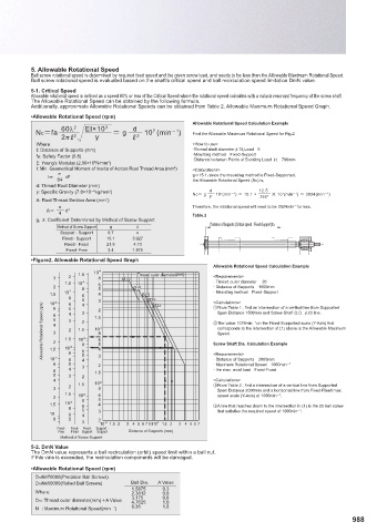
•Figure2. Allowable Rotational Speed Graph
Allowable Rotational Speed Calculation Example
1.5 10 4 Thread outer diameter(mm)
3 2 8 Ø10 <Requirements>
1.5 10 4 6 · Thread outer diameter խ20
2 8 5 Ø15 · Distance of Supportsխ1500mm
1.5 10 4 6 4 Ø20 · Mounting methodխFixed-Support
8 6 5 4 5 4 3 3 2 Ø25 Ø32 <Calculations>
10
3
Allowable Rotational Speed (rpm) 6 5 4 3 2 1.5 3 2 3 1.5 2 8 3 1.5 8 6 5 3 Ύ The value 1076min 1 on the Fixed-Supported scale (Y-Axis) that
From Table 1., fi nd an intersection of a vertical line from Supported
8
Span Distance 1500mm and Screw Shaft O.D. F20 line.
corresponds to the intersection of (1) above is the Allowable Maximum
10
Speed.
10
Screw Shaft Dia. Calculation Example
10
1.5
10
· Distance of Supportsխ2000mm
8 2 8 6 5 6 5 4 3 4 3 2 <Requirements>
· Maximum Rotational Speedխ1000min 1
6 4 1.5 · the max. axial loadխFixed-Fixed
5 3 2
4 10 2 <Calculations>
3 2 1.5 8 From Table 2., fi nd a intersection of a vertical line from Supported
Span Distance 2000mm and a horizontal line from Fixed-Fixed max.
1.5 2
2 10 6 5 speed scale (Y-Axis) at 1000min 1 .
1.5 10 2 8 6 4 ΎA line that reaches down to the intersection in (1) is the 25 ball screw
8 5 3 that satisfi es the required speed of 1000min 1 .
10 6 4
8 5 2
3 10 2 1.5 2 3 4 5 6 78 910 3 1.5 2 3 4 5 6 7
Fixed- Fixed- Fixed- Support -
Free Fixed Support Support Distance of Supports (mm)
Method of Screw Support
5-2. DmN Value
The DmN value represents a ball recirculation (orbit) speed limit within a ball nut.
If this vale is exceeded, the recirculation components will be damaged.
•Allowable Rotational Speed (rpm)
DmN≤70000(Precision Ball Screws)
DmN≤50000(Rolled Ball Screws) Ball Dia. A Value
1.5875 0.3
Where: 2.3812 0.6
Dm: Thread outer diameter(mm)A Value 3.175 0.8
1.0
4.7625
N : Maximum Rotational Speed(min ) 6.35 1.8
1
988