Page 993 - MiSUMi FA Mechanical Components Economy Series
P. 993

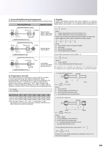
7. Screw Shaft Mounting Arrangements        9. Rigidity
           Representative ball screw mounting arrangements are shown below.  To improve positioning accuracy and control response of a machine,
                                                       considerations must be given to the rigidity of feed screw elements.
                    Mounting Methods      Application Example  Rigidity of feed screw system can be expressed with the following formula.
                   Supported Span Distance (Critical Speed: Fixed – Supported )   P
                                                         K         (N/Om)
             Fixed         Fixed     Supported              Ė
                                          · Typical method  Where:
                                          · Medium ~ High Speeds  P   :  Axial Loads Applied on Feed Screw System (N)
                                          · Medium ~High Accuracy  Ė   :  Elastic Deformation of Feed Screw System (μm)
                                                         Additionally, the following relationship exists between the feed screw
                                                         system rigidity and other various construction element rigidity.
                Load Applicable Span Distance (Buckling Load: Fixed – Fixed)  1  1  1  1  1
                                                         K    KR    Kn    Kb    Kh
                    Supported Span Distance (Critical Speed: Fixed – Fixed)
                                                         Where:
             Fixed       Fixed       Fixed               KR : Screw Shaft Compressive/Tensile Rigidity
                                                         Kn   : Nut Rigidity
                                          · Medium Speeds
                                          · High Accuracy  Kb   : Support Bearing Rigidity
                                                         Kh   : Nut and Bearing Mount Rigidity
                Load Applicable Span Distance (Buckling Load: Fixed – Fixed)  •Screw Shaft Compressive/Tensile Rigidity : KR
                                                              P
                    Supported Span Distance (Critical Speed: Fixed – Free)  KR         (N/Om)
                                                             ĖὙ
             Fixed         Fixed     Free                Where:
                                                         P  :  Axial Load (N)
                                          · Low Speeds   ĖR  :  Screw Shaft Expansion/Contraction (μm)
                                          · For Short Screw Shafts
                                          · Medium Accuracy
                                                       The expansion and contraction are expressed in the following formula.
                                                       The expansion and contraction will directly appear as ball screw backlash.
                Load Applicable Span Distance (Buckling Load: Fixed – Fixed)
                                                          ΍ Fixed-Free Arrangement
           8. Temperature and Life
           When ball screws are continuously used at 100°C or higher,
           or used momentarily at very high temperatures, Basic
           Dynamic/Static Load Ratings will be reduced according to the   Ɛ
           temperature rise due to changes in material compositions.  Fixed          Free
           However, there will be no eff ects up to 100°C.  Basic Dynamic Load    4PὙ
                                                                    3
           Rating C" and Basic Static Load Rating Co" at 100°C or higher with the   ĖR             –10 (Om)
                                                               2
                                                             EQd
           temperature factors ft and ft' can be expressed with the following formula.
                                                         Where:
            C"ftC(N)                                    P :  Axial Load (N)
                                                                          5
            C0"ft'C0(N)                                 E :  Young's Modulus (2.06x10 N/mm ) 2
                                                         d :  Screw Shaft Root Diameter (mm)
                                                         R  :  Load Applicable Span Distance (mm)
           Temperature °C 100 or less  125  150  175  200  225  250  350
             ft  1.0  0.95  0.90  0.85  0.75  0.65  0.60  0.50  Ύ Fixed-Fixed Arrangement
             ft'  1.0  0.93  0.85  0.78  0.65  0.52  0.46  0.35
           E Normal usage range is -20 ։ 80˫ .  For application in high
             temperature, use of heat resistant grease as well as heat resistivity of
             other components should be evaluated.
                                                                         Ɛ       Ɛ  ’
                                                                            L
                                                                  Fixed            Fixed
                                                              4PὙὙ'
                                                         ĖR              –10 (Om)
                                                                    3
                                                            EQd L
                                                               2
                                                         Where:
                                                         P : Axial Load(N)
                                                                         5
                                                         E : Young's Modulus (2.06x10 N/mm ) 2
                                                         d : Screw Shaft Root Diameter (mm)
                                                         R,R ' : Load Applicable Span Distance (mm)
                                                         L : Mounting Span Distance (mm)
                                                                                        L

                                                         The formula produces the max. value whenRR 'խ խխ
                                                                                        2
                                                         (                            )
                                                               PL
                                                          ĖR           –10
                                                                    3
                                                                2
                                                                EQd
                                                         Therefore, the max. shaft expansion and contraction will be 1/4 of
                                                         Fixed-Free arrangement.
                                                                                                   990
   988   989   990   991   992   993   994   995   996   997   998